 Facebook
 Google
 GitHub
 Linkedin
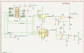
I have a circuit with a Raspberry Pi Zero driving a IRLZ34N MOSFET through a MCP4921 DAC and a TLV2462 op-amp as a voltage follower. The Pi also reads the current value from a 0.100 Ohm resistor (R5) in the source of the MOSFET, through a MCP3008 ADC and a Sallen-Key low pass filter using a TLV2462 op-amp. The load in the drain of the MOSFET is a rocket igniter. For testing, I am using a 12 V car light bulb to simulate the igniter. The goal of the circuit is to (1) activate the MOSFET to drive ~10 mA through the igniter to test continuiity in the ignition circuit and (2) drive ~1000 mA through the igniter to ignite the rocket.
The circuit works ok for large currents (see the test data). There is up to a 6 mA difference between the desired current and the current measured (see the chart from the test data). That really does not matter, as the igniter won't really care. But, when I program the DAC for 0 current through the igniter, there is about 8-10 mA flowing through the sensor resistor R5. Again, this is not a huge issue, as the igniter should not ignite at that low of a current. But no one wants to be installing the leads on the igniter when the rocket is on the launch pad, knowing there is some amount of current flowing in the igniter circuit.
I had three thoughts on how to solve the 0 current issue. One, to add a positive voltage bias to the bottom of R5 so the gate will effectively be at a lower voltage than the source for a certain range of values sent to the DAC, so the MOSFET is shut off. Two, I could change the power supply to U3 to be dual sided (+/-3.3V), and drive the output of U3 less than zero volts for a certain range of DAC outputs, which would also cut off the MOSFET. Three, I could add a relay controlled by the Pi in the igniter circuit that effectively disconnects the 12 V supply from the drain of the MOSFET when I want it to be off. The real downside of this approach is that it depends on the PI software to be bullet proof, which is not what the safety officers will accept.
I don't need the whole dynamic range of the DAC for this application controlling the MOSFET. The MOSFET needs to be "on a little" to test continuity, "on a lot" to ignite the rocket, and rock solid "off" the rest of the time.
I am looking for some guidance on which option (1 or 2) is most feasible and some guidance on how to implement the design.
Thanks!
Mark
Attachments
-
 24 KB Views: 72
 -
28.5 KB Views: 14
-
15.4 KB Views: 5


