 Facebook
 Google
 GitHub
 Linkedin
Hi There,
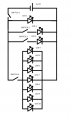
I have designed the attached circuit and just want to sense check that it will work, or for someone to point out any errors I have made.
I know there are no resistors in this circuit, I am using MS Paint for diagrams and just couldn't be bothered drawing them all!
Am I correct in thinking:
1) Switch 1 controls power to the whole circuit and when closed LED 1 will act as a power indicator light.
2) Switches 2 & 3 control power to LEDs 2 & 3 independently, i.e. either can be on / off / both.
3) Switch 4 controls power to LEDs 4 - 10 and they will all be on / off at the same time.
4) The arrangement of Switch 4 and LEDs 4 - 10 is still a parallel circuit so the 5v power supply will be enough for this many LEDs?
Any help would be really appreciated, thanks in advance!
Sam
Attachments
-
 73 KB Views: 25


