Correct LOGIC circuit?

Thread Starter

juliaaaan

Joined Jan 22, 2025
45
I have installed steering wheel heating in my car. With a single push button, I can turn the heating on and off using a single switch.


To this circuit, I want to add startup and shutdown sounds using a DY-SV17F (voice module). Connecting pin 1 to ground plays the startup sound, and pin 2 plays the shutdown sound.


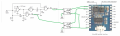
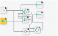
To achieve this, I've devised the following logic system:


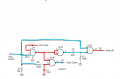
General description: an RS latch, a NOT gate, and an AND gate.


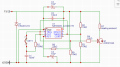
  1. The car is started and the circuit receives power (see figure 1): The reset of the RS latch is temporarily held high (using an RC circuit) to ensure both outputs remain low.
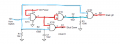
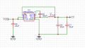
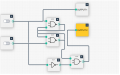
  2. The steering wheel heating is turned on (see figure 2): Output 1 goes high, grounding pin 1 of the MP3 module to play the startup sound. Additionally, the output of the RS latch is set high and latched.
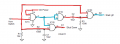
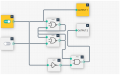
  3. The steering wheel heating is turned off (see figure 3): Through the NOT gate and the latched RS circuit, both inputs of the AND gate are high, causing output 2 to go high and play the shutdown sound.
Since the RS latch is not reset after the car is started, it will remain high, allowing toggling between on and off.

My question to you is whether this circuit will actually work, or if there is an easier way to generate the same output sequence using a single 12V on/off signal.?

Attachments
 

Attachments

crutschow

Joined Mar 14, 2008
38,316
You say you have a single push-button, but you show two inputs in your diagram.
Where are those two signals coming from?
 

Art Vandelay

Joined Nov 1, 2024
140
Try a JK flip flop. Tie J and K inputs to logic 1 then you can pulse the clock input with a single push button to toggle the output.

Wire the startup sound to Q and the shutdown sound to ~Q.

JKflipflopNOR-1-1024x633.png
 

Thread Starter

juliaaaan

Joined Jan 22, 2025
45
You say you have a single push-button, but you show two inputs in your diagram.
Where are those two signals coming from?
The second input is connected to the reset of the RS latch. This signal comes from a RC circuit that insures that the output of the RS latch is low.
 

Thread Starter

juliaaaan

Joined Jan 22, 2025
45
Try a JK flip flop. Tie J and K inputs to logic 1 then you can pulse the clock input with a single push button to toggle the output.

Wire the startup sound to Q and the shutdown sound to ~Q.

View attachment 348486
The problem here is that one of the outputs is always high. So, when the circuit receives power (when the car is started), the startup sound will begin even though the steering wheel heating hasn't been activated yet.
 

Art Vandelay

Joined Nov 1, 2024
140
The problem here is that one of the outputs is always high. So, when the circuit receives power (when the car is started), the startup sound will begin even though the steering wheel heating hasn't been activated yet.
You should provide the rest of circuit because I'm having trouble understanding the control algorithm you want to implement.

But from reading your description again, why not just use the steering wheel heating circuit logic as input to the sound module? (How is the heat activated..?)

Your approach seems to be adding an unnecessary layer of complexity. Maybe I'm missing something.
 

Thread Starter

juliaaaan

Joined Jan 22, 2025
45
Using a CD4011 quad Nand gate to provide a 1 second low output pulse for Start Up and Shut Down.
1746576436249.png
Thank you for your response. I tried to simulate your circuit to understand how the schematic works. Unfortunately, I couldn't figure it out.


I had the following questions about your circuit:


  • Does the 12 volts from the switch need to be a constant 12 volts? (I am using a push button that only supplies 12 volts briefly)
  • Do you mean by a low output pulse that the output ports temporarily provide 12 volts (for 1 second)?
  • Does this circuit also include the function that, when the car is started but the seat heater is not turned on, the shutdown sound will not play?
 

Thread Starter

juliaaaan

Joined Jan 22, 2025
45
Yes.
My interpretation from post #1 was that it was not a momentary switch.
Post a link to this steering wheel heater please.
I designed the steering wheel heating circuit myself (based on a 555 timer and a MOSFET), see attachment.


If I understand correctly, I could use your circuit by using the output of the steering wheel heating as a signal, since it is a switched 12-volt source.


However, is it indeed the case with your circuit that the shutdown signal can only go high (for one second) after the startup signal has been high?
 

Attachments

sghioto

Joined Dec 31, 2017
8,633
If I understand correctly, I could use your circuit by using the output of the steering wheel heating as a signal, since it is a switched 12-volt source.
Correct, connected like so:
However, is it indeed the case with your circuit that the shutdown signal can only go high (for one second) after the startup signal has been high?
Not sure the question but I believe the answer is NO.
When the heater circuit is ON C1 on pin 12 of the 4011 is charged up.
When the heater circuit is shut down pin 13 of the 4011 goes High along with pin 12 which is held High briefly by the charge on C1.

1750792198489.png
 
Last edited:

Thread Starter

juliaaaan

Joined Jan 22, 2025
45
Correct, connected like so:

Not sure the question but I believe the answer is NO.
When the heater circuit is ON C1 on pin 12 of the 4011 is charged up.
When the heater circuit is shut down pin 13 of the 4011 goes High along with pin 12 which is held High briefly by the charge on C1.

View attachment 351675
If I understand correctly, your circuit works as follows (see attachment) red high, blue low.


If this is how it works, the startup signal will always be low when the steering wheel heating is activated, is that correct or am I missing the function of C2 and R3?


In addition, I’m afraid that what I actually need is a short high signal (12V) to trigger the sound module. These signals drive an optocoupler, which then temporarily pulls the appropriate pin to ground to play the startup or shutdown sound (see attachment).

For extra information, the sound module operates on 5 volts.
 

Attachments

sghioto

Joined Dec 31, 2017
8,633
If this is how it works, the startup signal will always be low when the steering wheel heating is activated, is that correct or am I missing the function of C2 and R3?
Only briefly.
As C2 begins to charge the voltage on pin8 will decrease. Once it gets below the threshold the output on pin10 will switch back High.
The optocouplers can be wired for a negative signal like this:
1750799991440.png
 

sghioto

Joined Dec 31, 2017
8,633
If the sound module and heater circuit share the same ground then the optocouplers are not needed.
How will the sound module be powered?
I have another version that uses an additional 555 chip in conjunction with the heater circuit if interested.
 
Last edited:

Thread Starter

juliaaaan

Joined Jan 22, 2025
45
If the sound module and heater circuit share the same ground then the optocouplers are not needed.
How will the sound module be powered?
I have designed a buck converter that lowers 12 volts to 5 volts, see attachment. This converter uses the same ground (see attachment).

Would this then mean that I can connect the output of the 4011 directly to the signal pins of the sound module (with a resistor in series to go from 12V to 5V)? When the startup or shutdown signal from the 4011 goes low (for a second), the signal pins of the sound module are pulled to 0V and thus essentially connected to ground (since they share a common ground)?
 

Attachments

Last edited:
Top