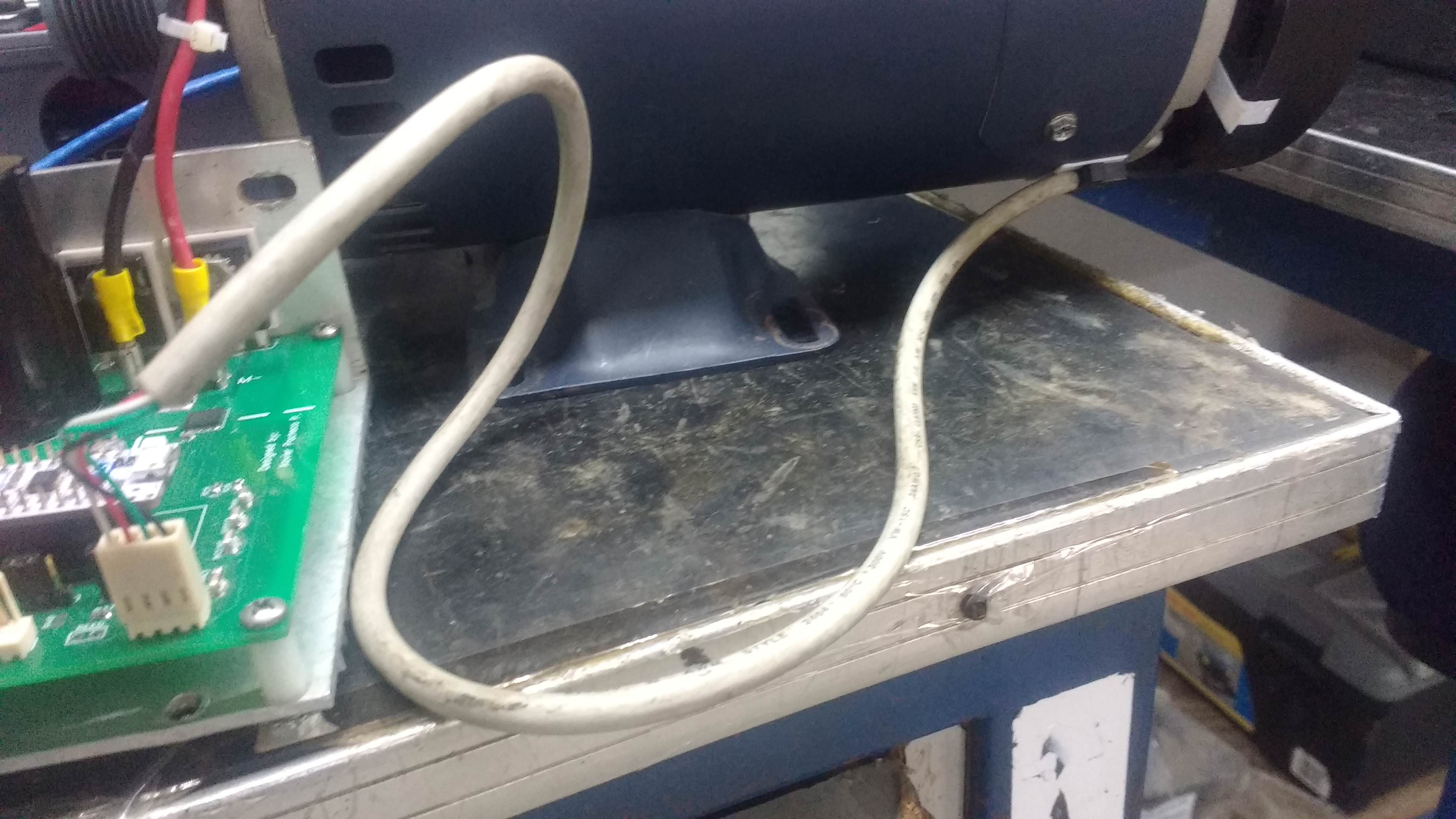
Is there a way to attach a speed sensor, slotted or reflective, to this motor?

Thread Starter

Xavier Pacheco Paulino

Joined Oct 21, 2015
728
I have experienced that same problem with a pressure transducer. My solution was total electrical isolation from the framework of the machine and completely separating the electrical wires as well. So the shield on the sensor wires was only grounded at the sensor input to the control system, and the sensor ground was only connected to ground at the sensor control system sensor input. In addition, the motor wires were also shielded, and that shield was grounded at the motor drive controller. In that situation it produced adequate isolation. The fix was tedious but not complicated or expensive. So it might possibly be that you will need to experiment with shielding the motor drive wires, and connecting it only to the motor drive package housing. That housing would then also be connected to the "green wire" safety ground.
I had that question about the green wire. It's floating in my setup.
Also, I just tried another sensor position and now the noise is not so frequent as before. So I think I need total isolation between the sensor and the motor.
 

MaxHeadRoom

Joined Jul 18, 2013
30,881
The service Earth ground conductor should always be connected to the motor frame in practically all cases, especially where the motor power is not isolated from the service.
You could try placing a small earth grounded metallic covering over the sensor.
Max.
 

Thread Starter

Xavier Pacheco Paulino

Joined Oct 21, 2015
728
The service Earth ground conductor should always be connected to the motor frame in practically all cases, especially where the motor power is not isolated from the service.
You could try placing a small earth grounded metallic covering over the sensor.
Max.
The sensor GND is isolated from the motor power GND. The green wire is connected to motor frame. But, do I have to connect this wire to motor power ground? I will try the metallic covering over the sensor.
 

MisterBill2

Joined Jan 23, 2018
28,561
The motor power connections need to remain separate from the grounds, not only because they are not the same as the safety ground, but also because the motor noise voltage and current are present on all of the motor power wires. BUT you can have a shield on those wires and that shield can be grounded.
 

MaxHeadRoom

Joined Jul 18, 2013
30,881
You can however ground the motor power common IF the power supply is isolated via galvanic isolation, transformer secondary etc.
Know as re-referencing earth GND.
Max.
 

Thread Starter

Xavier Pacheco Paulino

Joined Oct 21, 2015
728
I've got a bit confused. First, my board is powered directly from the 120VAC outlet. There's not isolation transformer. The mains are rectified and filtered. Now, the microcontroller and sensors power is provided by another AC/DC converter which is isolated. That's why microcontroller/sensor GND is different from the power rectifier GND. The motor has three wires, RED, BLACK and GREEN. So, if I understood correctly, my green wire (safety motor earth) should not be connected anywhere if the motor power supply is not isolated.
 

MaxHeadRoom

Joined Jul 18, 2013
30,881
No. the Green earth ground wire Should be connected to the motor frame, the frame has no other reference, unlike the Supply to the motor which is fed from the AC supply live & neutral.
The observation in above posts is that the earth GND Cannot be connected to your DC motor Common, as it has no galvanic isolation from the incoming AC.
You can however earth ground any other circuit that is isolated, including the Micro supply common etc.
Max.
 

MisterBill2

Joined Jan 23, 2018
28,561
I've got a bit confused. First, my board is powered directly from the 120VAC outlet. There's not isolation transformer. The mains are rectified and filtered. Now, the microcontroller and sensors power is provided by another AC/DC converter which is isolated. That's why microcontroller/sensor GND is different from the power rectifier GND. The motor has three wires, RED, BLACK and GREEN. So, if I understood correctly, my green wire (safety motor earth) should not be connected anywhere if the motor power supply is not isolated.
No, do not ground the motor power common, but DO connect the green wire safety ground to the motor frame. AND, if you are able to shield the motor power wires, ground that shield to the ground wire at the motor controller end. The object of the shielding and grounding and isolation is to prevent any noise currents from flowing in any of the sensor circuits, AND to avoid any radiated signals from the power wires from coupling into those signal circuits. Preventing noise from interfering with signals is often a big challenge.
 

MaxHeadRoom

Joined Jul 18, 2013
30,881
The green wire is internally connected to the motor frame. So, I guess I can just cut the green wire floating in the outside then.
"So, I guess I can just cut the green wire floating in the outside then"

What Green wire?
Again, the motor frame GND conductor Should be connected to the Service earth ground conductor.
Max..
 

MaxHeadRoom

Joined Jul 18, 2013
30,881
IMO The confusion is also enhanced by the use of Ground for circuit common and also for earth ground, often neither are connected, I prefer to reserve Ground for Earth Ground and use Common for the 0v reference plane.
In your case the green conductor would go from the Motor Frame to the Earth Ground conductor originating from the service entry panel.
Max.

.
 

Attachments

MisterBill2

Joined Jan 23, 2018
28,561
When we reference a "green wire" or the "Green wire ground" that is the physical ground connection to the metal parts of the motor, in this case. The green wire is not part of the power path, it is separate and the purpose is to prevent electrical shocks. I see no reason to consider cutting it. Twisting the motor leads, as Max suggests may possibly be useful, BUT not if they are in a cord attached to the motor. I don't recall if the motor is permanently connected to the controller, or if those wires can be easily disconnected and then re-connected.So adding a shield to the motor power wires may be a bit more complex that I had thought.
 

MaxHeadRoom

Joined Jul 18, 2013
30,881
One example of the earth ground used to combat any electrical interference rather than a safety precaution is your desk top PC Power Supply, It is isolated from the incoming AC by virtue of the SMPS, but the common (0v) is referenced to service earth ground conductor on the chassis.
Max.
 

Thread Starter

Xavier Pacheco Paulino

Joined Oct 21, 2015
728
I don't recall if the motor is permanently connected to the controller, or if those wires can be easily disconnected and then re-connected.So adding a shield to the motor power wires may be a bit more complex that I had thought.
The motor can easily be connected or disconnected from the controller. Actually it's no so easy to shield the motor power wires. I covered the sensor wires and moved the sensor and the noise doesn't appear so often. However, it sometimes still leaks.
 

MaxHeadRoom

Joined Jul 18, 2013
30,881
I would try and twist those motor leads.
The sensor cable might have been better over-all shield or a cable with two shielded pair cable.
Max.
 

MisterBill2

Joined Jan 23, 2018
28,561
I see! The motor leads are the red and black ones with the yellow push-on terminals, and the ty wraps holding them together. That would indeed make pushing on some shield brad a rather tedious operation indeed. It looks like the pickup leads are not shielded and that is unfortunate. If you add a fairly heavy lead from the motor frame to the metal frame of your controller that should improve the operation by reducing the noise voltage on the motor body a bit. Use a wire at least as thick as the motor power leads and it should be fine. And hopefully the ground wire from the power cord also is connected to the chassis of the speed controller as well.
 
Top