AND, I had made the assumption that the circuit was connected as shown. All of my suggestions were based on that assumption. Such an easy goof to make..
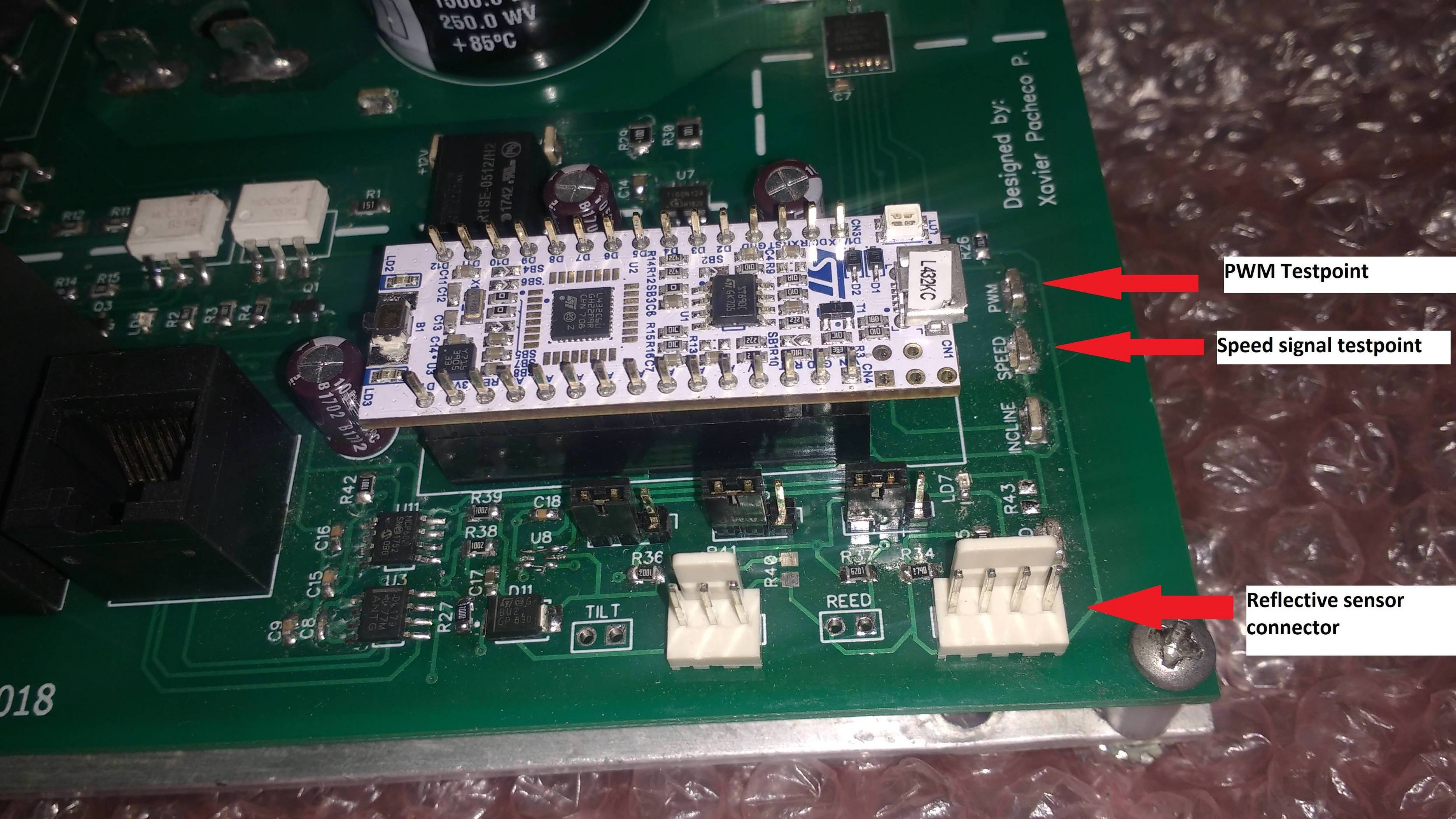
What do you think of this? Is it correct? I will use this reflective sensor. Another info is that the motor will be enclosed, so ambient light should not disturb. I haven't tested it yet.
Another option to consider is to mount it on the rear side of the flywheel on the motor frame, paint and tape the flywheel similar to the front, but this allows for simple mounting using the existing 'brush'? cover screws to mount it flat to the motor frame and ease of protective cover.
Similar as done in commercial T.M. versions.
Max.
Another option to consider is to mount it on the rear side of the flywheel on the motor frame, paint and tape the flywheel similar to the front, but this allows for simple mounting using the existing 'brush'? cover screws to mount it flat to the motor frame and ease of protective cover.
Similar as done in commercial T.M. versions.
Max.
The OBP704 requires it to be 3.81mm from the surface (see the datasheet). LED should not be run at more than 1.7VDC max, and should be run at between 30mA and 40mA. Max is 50mA, but you should never run an LED at max.
IR LED Transmitter Resistor Size (Ohms):
R = E/I
R = (3.3 - 1.6) / 0.40
R = 1.7 / 0.40
R = 4.25 Ohms.
IR LED Transmitter Resistor Wattage:
P = I*E
P = 0.40 * 1.7
P = 0.68W
P = 680mW
I would breadboard this and test it in different lighting conditions with lower currents on the trasmitting LED to see how well it responds.
Instead of putting the reflectors on the back of the flywheel, why not put them on the edge, which simplifies mounting the sensor to the motor...
The OBP704 requires it to be 3.81mm from the surface (see the datasheet). LED should not be run at more than 1.7VDC max, and should be run at between 30mA and 40mA. Max is 50mA, but you should never run an LED at max.
IR LED Transmitter Resistor Size (Ohms):
R = E/I
R = (3.3 - 1.6) / 0.40
R = 1.7 / 0.40
R = 4.25 Ohms.
IR LED Transmitter Resistor Wattage:
P = I*E
P = 0.40 * 1.7
P = 0.68W
P = 680mW
I would breadboard this and test it in different lighting conditions with lower currents on the trasmitting LED to see how well it responds.
Instead of putting the reflectors on the back of the flywheel, why not put them on the edge, which simplifies mounting the sensor to the motor...
Does the noise vary as the sensor is moved? Wiring with shielded cable may help, but as Max mentions above, what is your power supply like?
First, determine if it is induced from the motor radiation or power supply related.
1. The micro power supply is isolated from the motor, they do not share the same GND.
2. The PWM frequency is 5 kHz.
3. I have a software routine which continuously check the frequency of the input signal. Then I convert frequency to RPM.
4. When I start the motor, the microcontroller tells me that I'm measuring 5 kHz. If I stop the motor, the 5 kHz frequency disapear, and I could measure speed if I move the flywheel with my hands.
5. I have a cheap oscilloscope, not so reliable, and it also picks up the 5 kHz signal.
Can you post a picture of your setup?
Short wires and good layout can make a big difference.
Have you looked to see if the where the noise is from, as in my previous post?
Does the noise vary as the sensor is moved? Wiring with shielded cable may help, but as Max mentions above, what is your power supply like?
First, determine if it is induced from the motor radiation or power supply related.
I have experienced that same problem with a pressure transducer. My solution was total electrical isolation from the framework of the machine and completely separating the electrical wires as well. So the shield on the sensor wires was only grounded at the sensor input to the control system, and the sensor ground was only connected to ground at the sensor control system sensor input. In addition, the motor wires were also shielded, and that shield was grounded at the motor drive controller. In that situation it produced adequate isolation. The fix was tedious but not complicated or expensive. So it might possibly be that you will need to experiment with shielding the motor drive wires, and connecting it only to the motor drive package housing. That housing would then also be connected to the "green wire" safety ground.

 Facebook
 Google
 GitHub
 Linkedin