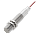
Another good possible. I have used the AIRPAX Magnetic sensors on numerous systems. They are good for picking up teeth on a gear and should work fine for the above task.
One other consideration on the resolution is if it is just for RPM monitoring/indication or RPM control is considered, if the latter, then closer control is achieved using a multi count/rev method.
If using a one/turn retro-reflector, use a single small white paint stripe or tape, not half the wheel.
Also I have tested the QRE1113 I used for any effect of incidental light that might be present, but I did not detect any detrimental effect from the sources I used.
Max.
The reason that I suggested half the wheel is that at higher speeds the pulse may be too short for some counter circuits. Since paint is both cheap and easy, the 50% coverage would produce closer to a square wave and be more reliable. Admittedly this is a bit more than a perfect counter needs, but a very easy way to reduce the possibility of a problem. At the time I posted that suggestion I had no idea what the application was, and some applications include very fast motor speeds.
Another good possible. I have used the AIRPAX Magnetic sensors on numerous systems. They are good for picking up teeth on a gear and should work fine for the above task.
I have quite a few 12mm dia in my surplus stash, Baluff, Turk etc.
Also another source is an auto wrecker for the Honeywell 1GT101DC gear timing detector.
Max.
I have quite a few 12mm dia in my surplus stash, Baluff, Turk etc.
Also another source is an auto wrecker for the Honeywell 1GT101DC gear timing detector.
Max.
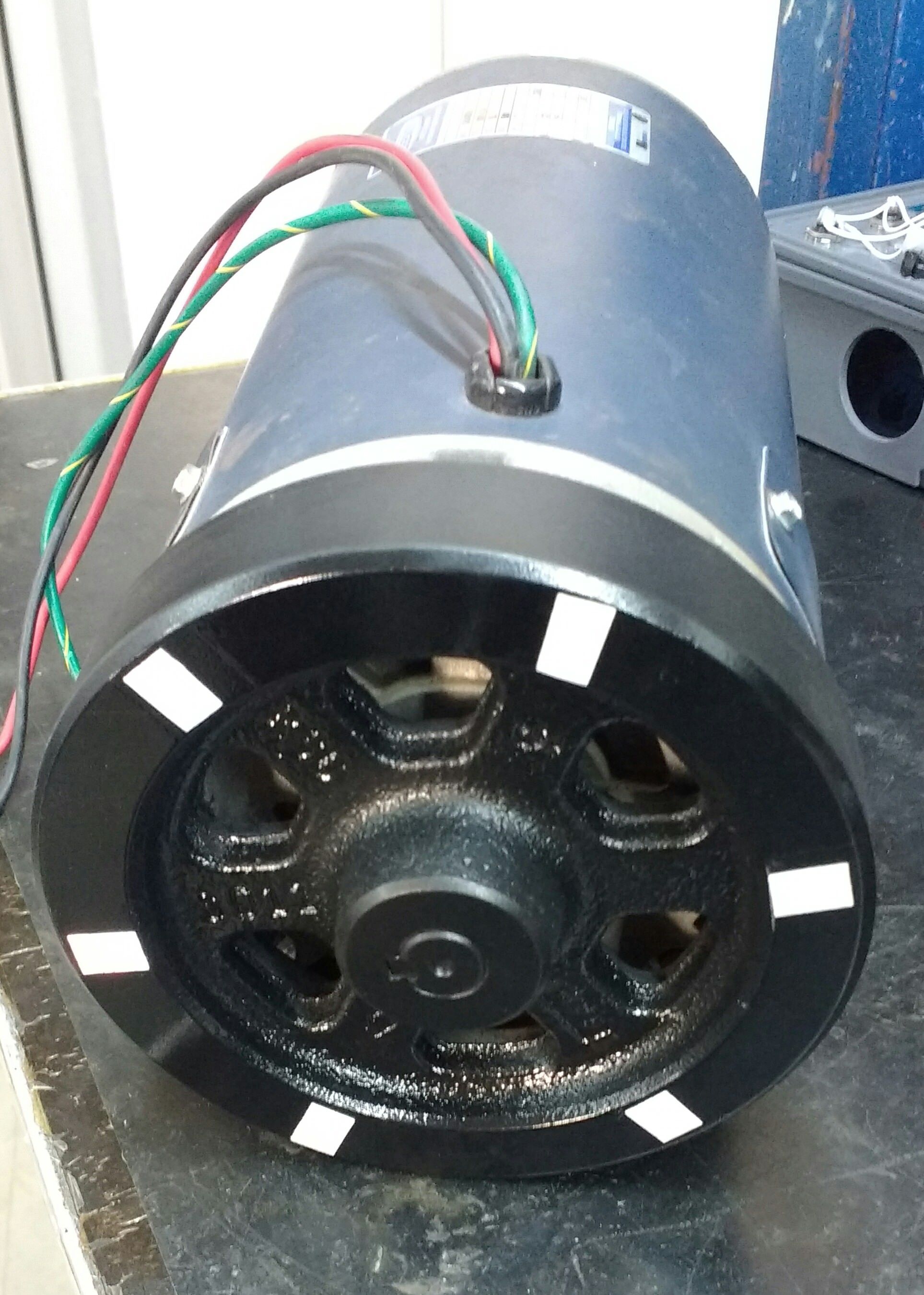
What do you think of this? Is it correct? I will use this reflective sensor. Another info is that the motor will be enclosed, so ambient light should not disturb. I haven't tested it yet.
What do you think of this? Is it correct? I will use this reflective sensor. Another info is that the motor will be enclosed, so ambient light should not disturb. I haven't tested it yet.
The application of reflective patches looks reasonable, but it may be that the shiny black paint also reflects light. Only testing will determine that. And it might possibly be that it works perfectly up to some speed. You do need to be certain that the mount for the sensor is stable and rigid.
You will know when you test it. I have used a piece of reflective tape doing test on some shiny stainless steel shafts and it worked. I guess it all comes down to testing it.
Some thoughts from the past. I've used the photo transistor as an emitter follower with 100k emitter R
feeding into a non inverting gate for signal shaping. Motor whizzing around at 20 RPM but not allowed
to make a full rotation. Also used a comparator and emitter follower.
I'm having some issues. First, I have a setup very similar to one shown below. There are some differences. The voltage is 3.3V. The collector pull up resistor is 10k and the diode current-limiting resistor is 174 ohms. What I find strange is that without the sensor connected, (just the pull up resistor) I'm measuring 1.4V at Vout, which is the microcontroller input. I'm getting nothing from the sensor also.
Update: The sensor is activating, I just need to place it well. But I'm still confused about the pull up voltage, should be 3.3V.

 Facebook
 Google
 GitHub
 Linkedin