Is the LM311 essentially the same as LM393?

Status
Not open for further replies.

GopherT

Joined Nov 23, 2012
8,009


I seem to have it working, with IRFZ44 replacement fet only warm under certain conditions.
Added a small heatsink as well. Hysteresis resistor reduced to 47k, and 2.2uf Added from -IN to ground.

Also added a larger working cap. I also swapped out a 5A motor for the 8A unit that was failing. So far, so good.
I'll order the LM311, and tinker with this circuit again. Much thanks.
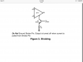
I agree with @OBW0549 that the lm311 doesn't add any advantage over the current chip. If you do want to order it, however, you should get an 2n222a and a hex inverting Schmitt trigger chip and use that to disable the system if your solar panel voltage is too low. The LM311 has a convenient STROBE pin that shuts down the chip.

From the lm311 DATASHEET...

image.png
 

Thread Starter

Hamlet

Joined Jun 10, 2015
560
I agree with @OBW0549 that the lm311 doesn't add any advantage over the current chip. If you do want to order it, however, you should get an 2n222a and a hex inverting Schmitt trigger chip and use that to disable the system if your solar panel voltage is too low. The LM311 has a convenient STROBE pin that shuts down the chip.
I think I might have one of those, the MC74HC14A hex inverting Schmitt trigger? I think that's a good idea, shutting it off if the voltage goes to low to turn the motor, but it's a little above my knowledge to implement. I'm going to have to study both datasheets, and do some head scratching. Any hints on how to implement it would surely be appreciated.


Let me add, if I wasn't clear in my previous post, that I was able to get this circuit oscillating without overheating the mosfet. With my homemade
bench supply, I was able to start a 5a motor with my power supply limited to 1A, and it had good torque for all of, what, 12w to 15w...

Let me also add, I am having fun with these "pwm" type circuits that I have been building. Once spring comes, I hope to have something robust
enough to implement for my home and garden solar irrigation projects.
 

Thread Starter

Hamlet

Joined Jun 10, 2015
560
After some consternation, I recently learned to watch for dual comparators with inverting and non inverting functions on same chip.
Also, crutchow had the following to share in another thread about comparators:

...when the (+) input voltage of the comparator is higher than the (-) input, the output transistor is off and the output voltage is "pulled up" to the positive voltage connected to the resistor (logic high).

And when the (-) input voltage of the comparator is higher than the (+) input, the transistor is ON which shunts the resistor current to ground, making the output voltage near zero (logic low).

That sounds good to me, and I might add, one needs to watch to make sure the voltage inputs don't drop -0.3v below ground, or come closer that 1.5v to the Vcc rail.

Just some notes for future self reference
 
Status
Not open for further replies.
Top