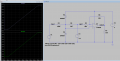
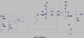
Is it possible to make this millivolt measuring circuit voltage polarity-independent?

Thread Starter

Shamoooot

Joined Apr 3, 2023
65
You masked out the opamp model that the simulation is using. Why?

Your 0 V input is resulting in an output voltage that is about 300 mV to high, which means that an extra 24 µA of current is flowing through the feedback resistor. This is very possibly due to the bias current requirements of the opamp. But without knowing the model, there's no way for us to determine if that is reasonable or not.
I am using in the simulation the LT6020, but I am planning to use MCP6021 which is not available on the LTSPICE.

LT6020
MCP6021
 

Thread Starter

Shamoooot

Joined Apr 3, 2023
65
But your thread title says that you are wanting to measure millivolt signals.

Have you considered the impact of your component tolerances?

Have you considered the impact of supply voltage variation, since your circuits are relying on a voltage divider using the supply? What happens if your supply drifts by, say, 20 mV?
Thank you again.
I actually want to use a voltage reference ic (LT1461) with ADS1115 and precision resistors perhaps 0.1% tolerance..
 

WBahn

Joined Mar 31, 2012
33,313
Post #3. .dc v1 -7 7 0.001
V1 looks to be the input voltage in that post, with a 14V range.
I assume the dc sweep analysis was the source of the queried curve.
And his simulation shows the output railing at the beginning and end of the simulation. But that wasn't what he was asking about -- his query was why the transfer curve was shifted to the right such that at 0 V input the output wasn't the expected 2.5 V.
 

WBahn

Joined Mar 31, 2012
33,313
I am using in the simulation the LT6020, but I am planning to use MCP6021 which is not available on the LTSPICE.

LT6020
MCP6021
The input bias current on the LT6020 shouldn't exceed 10 nA, so that's not the cause.

As I think someone else suggested, it might be the current in the diodes. One way to check that is just remove them from the simulation and see if anything changes.
 

Thread Starter

Shamoooot

Joined Apr 3, 2023
65
The input bias current on the LT6020 shouldn't exceed 10 nA, so that's not the cause.

As I think someone else suggested, it might be the current in the diodes. One way to check that is just remove them from the simulation and see if anything changes.
I tried but same issue..

Maybe I just re-do the calculations to increase the input range by 1V more than what I need, to account to the shift..
 

WBahn

Joined Mar 31, 2012
33,313
I tried but same issue..

Maybe I just re-do the calculations to increase the input range by 1V more than what I need, to account to the shift..
You need to understand the shift, especially if you are hoping to get results within 0.3%.

Look at the various currents in your simulation to track down where the discrepancy is.
 

panic mode

Joined Oct 10, 2011
5,420
V3 is used as virtual ground Vgnd which is about half way between 0 and 5V.

R3 and R4 are voltage divider, so OpAmp is measuring voltage across R4.

R5 and R6 are used to set gain.

R7 is just a dummy simulating impedance of next stage.

diodes are used to clamp voltage going to IC if V1 is excessive. note since Vgnd is 2.5V (positive), diodes clamp to +5 and 0V (that is +/-2.5V relative to Vgnd).

R3 is chosen to be reasonably low value but within typical power limit even for excessive input voltage (V1) such as +/-250V applied indefinitely.

P=V^2/R = (250^2)/330000 = 190mW (less than 1/4W).
R4 is chosen to get suitable input voltage for the opamp.

other values are meant to be in 10k range. this is reasonably low but not too low. low values mean that any leakage current etc, will have little effect. but, they are chosen to get +/-225V input scaled to 0-5V range that your ADC can handle. also i like to get values that are standard. this makes it easier to source parts. if any trimming is needed, it can be done of course but since this is going into ADC, it is easy to do this in software.

governing equations are just the basics... OpAmp gain, Ohms law, Kirchoffs law, power...
 

crutschow

Joined Mar 14, 2008
38,913
For double the resolution, you could use an op amp ideal rectifier circuit to convert the negative voltage to positive.
The rectifier circuit can generate a logic signal to indicate the voltage is negative (giving the extra bit of resolution).
 

Thread Starter

Shamoooot

Joined Apr 3, 2023
65
V3 is used as virtual ground Vgnd which is about half way between 0 and 5V.

R3 and R4 are voltage divider, so OpAmp is measuring voltage across R4.

R5 and R6 are used to set gain.

R7 is just a dummy simulating impedance of next stage.

diodes are used to clamp voltage going to IC if V1 is excessive. note since Vgnd is 2.5V (positive), diodes clamp to +5 and 0V (that is +/-2.5V relative to Vgnd).

R3 is chosen to be reasonably low value but within typical power limit even for excessive input voltage (V1) such as +/-250V applied indefinitely.

P=V^2/R = (250^2)/330000 = 190mW (less than 1/4W).
R4 is chosen to get suitable input voltage for the opamp.

other values are meant to be in 10k range. this is reasonably low but not too low. low values mean that any leakage current etc, will have little effect. but, they are chosen to get +/-225V input scaled to 0-5V range that your ADC can handle. also i like to get values that are standard. this makes it easier to source parts. if any trimming is needed, it can be done of course but since this is going into ADC, it is easy to do this in software.

governing equations are just the basics... OpAmp gain, Ohms law, Kirchoffs law, power...
I am trying to draw the final circuit before making the PCB, but I am having trouble figuring out how to do the 2.5V source. I tried voltage divider with equal 100k resistors for the 5V rail without success...
 

Thread Starter

Shamoooot

Joined Apr 3, 2023
65
Thank you very very much Panic and Eric..

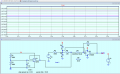
How about LMV321?, and how about C1 as advised:

LMV321

1737380926737.png

Also I would like to ask which are the critical resistors that need to have low tolerances like 0.1% ?
 

Thread Starter

Shamoooot

Joined Apr 3, 2023
65
hi sham,
This is an LTS method for checking the effect of tolerances, it is called the Monte Carlo test.
This one is set for 1% tolerance of a particular resistance value for R7 and noting the effect on Vout
Give it a try on other resistors, it also works for capacitors etc ...
E

View attachment 340785
This is wonderful, thank you very very very much......
 
Top