Is a tiny IC chip easily destroyed by soldering?

KeithWalker

Joined Jul 10, 2017
3,607
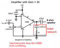
Your original connection diagram is difficult to follow. The components are not all drawn to the same scale and there are a number of breaks in the conductors. The schematic you showed on your first page is correct. Why did you change things and still expect it to work? C1 and C3 should be connected as shown there.
You are using a tantalum capacitor for C3 so make sure you connect it the right way round (+ wire to + supply).
 

Audioguru again

Joined Oct 21, 2019
6,826
The datasheets for the LM4862 amplifier and for the 7805 regulator show you exactly how to connect the parts.
Here is what is shown on the datasheet for the regulator.
 

Attachments

Thread Starter

lame man

Joined Mar 16, 2021
14
I've remedied what could have been a problem with the capacitors. There is no point in further exploration with this schema. I told sales at Mouser that they could quality check the LM 4862s that they are selling; I ran into a problem with their on/off switches. My objective is to build an amplifier and I have chosen to build one around the LM 386 which is through hole and I can use with a socket. I'm posting the schematic off the internet and my own diagram of how I will build it. Pin 7 (Bypass) is not shown so then I will ground it. The audio input goes through R3 a 10K potentiometer or pot as he refers to it. I viewed every kind of resistor at Mouser and the kind that he has in his head does not match with what Mouser has.
 

Attachments

KeithWalker

Joined Jul 10, 2017
3,607
If you insist on grounding pin 7, do it through a 0.1uF capacitor, not a direct connection to ground. It really is not necessary with the circuit you are using. That is why it is not shown in the schematic.
I have used that circuit on a number of occasions and it works well. Try to keep your circuit tidy, with the components flush with the circuit board and with the wires as short as possible. Then it will be easy to see if you make any mistakes. Double check that you put the IC in the socket the right way round before you connect the power. You don't want to damage the chip before you get it working.
Good luck!
 

Audioguru again

Joined Oct 21, 2019
6,826
Both of your schematics are completely wrong. Look at correct schematics in the datasheet of the LM386.
1) The 5V regulator is not needed and reduces the supply to only 5V where the output power is half. The LM386 works well with 9V.
2) The 10 ohms resistor in series with the supply is not needed because it causes all kinds of problems and reduces the output power by another half.
3) If you ground pin 7 then the LM386 will not work! Pin 7 can use a capacitor to ground if the supply is noisy.
4) You have both inputs grounded then there is no input signal.
5) You have a 10k resistor in series with the input that is not needed.
6) Your circuit is missing the very important series RC Zobel network to ground at the output.
7) You have an RC between pin 1 and pin 8 to make the gain about 60 times which is too much.
8) If the MP3 player does not have an output coupling capacitor then your amplifier will need one at its input.
Look here:
 

Attachments

Thread Starter

lame man

Joined Mar 16, 2021
14
5/1/21 "Your schematics are wrong." If you mean the configuration of the pins of the LM 386 I took it from its datasheet. Study the new way that I will build the amplifier after your comments. I'm eliminating the resistor and the capacitor between pins 1 and 8 producing a gain of 20 which is that set internally by the IC according to the author of the blog. He doesn't show your 100 uF capacitor in parallel (?) to the power and pin 6. Like you he shows a Zobel network. The in series capacitor to the speaker has a value of 250 uF instead of your 470 uF. The in parallel volume resistor with a value of 20 kOhm between the audio input and pin 3 looks like what? The PNG file that I attached? Because it has an unusual schematic symbol and both of you agree that it controls volume.Potentiometer.PNG
 

Attachments

Audioguru again

Joined Oct 21, 2019
6,826
Everybody in electronics assumes that an IC or simple transistor circuit MUST have a supply bypass capacitor.

I show the schematic from the datasheet where every circuit has the important Zobel network.

A 220uF capacitor feeding an 8 ohm speaker cuts all bass sounds below 91Hz but 470uF passes frequencies above 42.5Hz for better bass sounds.

A volume control is a variable voltage divider. Its arrow is a slider that slides along a resistive track. Turn it up and the sounds are louder. Turn it down and the sounds are off or low level.
 

Willen

Joined Nov 13, 2015
338
Once I had heated a 1N4148 diode too long to make its voltage drop from 520mV to 150mV. I did and got 160mV drop voltage and it worked better than 1N34 (germanium) in a batteryless crystal radio (for a few second).
 

KeithWalker

Joined Jul 10, 2017
3,607
5/1/21 "Your schematics are wrong." If you mean the configuration of the pins of the LM 386 I took it from its datasheet. Study the new way that I will build the amplifier after your comments. I'm eliminating the resistor and the capacitor between pins 1 and 8 producing a gain of 20 which is that set internally by the IC according to the author of the blog. He doesn't show your 100 uF capacitor in parallel (?) to the power and pin 6. Like you he shows a Zobel network. The in series capacitor to the speaker has a value of 250 uF instead of your 470 uF. The in parallel volume resistor with a value of 20 kOhm between the audio input and pin 3 looks like what? The PNG file that I attached? Because it has an unusual schematic symbol and both of you agree that it controls volume.View attachment 237241
We are trying very hard to help you to make your project successful but that is not very likely to happen because you ignore most of the advice offered to you.
The purpose of the wiring diagram is to help you to wire up the circuit correctly. You were given examples but your latest diagram uses schematic symbols which give no indication of their relative physical size or actual location of the components. The diagram does not indicate what the terminals on the input jack and volume control look like or how they are wired.
I regret that your project is doomed to failure. There is nothing more I can do to help you.
Good luck.
 

BobaMosfet

Joined Jul 1, 2009
2,211
3/20/2021 I took great care not to fry the amplifier chip but I still get no sound - not even a crackle when plugging in or withdrawing from the input jack. Can anyone bring their lights to bear on my implementation of what's in the schematic. Being a newbie I probably did something wrong.
  1. Save yourself some trouble. Get an 830-hole standard breadboard for one thing. See that the circuit actually works at all before soldering it up.
  2. Secondly, color-code your wire:
  3. RED = V+
  4. GREEN = V-/Gnd
  5. YELLOW, BLUE, or BLACK = Signal

Beyond that- why not follow someone who's done it before and look at their work?

https://www.homemade-circuits.com/lm4862-amplifier-circuit-better-lm386-alternative/
 
Last edited:

dl324

Joined Mar 30, 2015
18,337
Is it possible that each time I am burning out the LM 4862 chip while soldering? The soldering iron temperature is set at 510° Fahrenheit.
It's possible.

Manufacturers used to provide this information more readily. "Allowed" soldering times are typically 10 seconds at 260-300C (500-572F). I solder at 371C (700F), but complete the joint in a few seconds.

Nat Semi specified 260C and 300C. RCA specified 265C in their COS/MOS databook circa mid 1970's.
 

BobaMosfet

Joined Jul 1, 2009
2,211
I wouldn't keep a hot iron on a pin on a chip for more than 5 seconds absolute max. I try always for 2 secs or less. Because as you solder an IC, the whole package temperature rises. It will get progressively hotter to a point, which means it takes less time to rise above any potential danger point. Using flux liberally generally helps as lean solder joins more effectively and quicker.
 

Thread Starter

lame man

Joined Mar 16, 2021
14
5/26/21 As I stated I changed to using the through hole LM386 using a socket. This last format is the one that has finally worked and additionally has volume control. I could not tell the negative lead of the 0.47nuF belonging to the RC section. I guess I was just lucky. Photos are just to give something visual to the finished product. Good sound was weak - any higher and there was distortion. The speaker I have on hand (has solder spilled on it) is 1.4", 8 ohms and 2 watt. Any suggestion for a better adapted speaker would be welcome. I've checked ebay for small transistor radio speakers.Bottom view.JPGTop view.JPG
 

KeithWalker

Joined Jul 10, 2017
3,607
5/26/21 As I stated I changed to using the through hole LM386 using a socket. This last format is the one that has finally worked and additionally has volume control. I could not tell the negative lead of the 0.47nuF belonging to the RC section. I guess I was just lucky. Photos are just to give something visual to the finished product. Good sound was weak - any higher and there was distortion. The speaker I have on hand (has solder spilled on it) is 1.4", 8 ohms and 2 watt. Any suggestion for a better adapted speaker would be welcome. I've checked ebay for small transistor radio speakers.

The LM386 will drive a 4 ohm speaker. That would give you twice the power out. Larger diameter speakers have much better low frequency response and the larger cone will produce more sound.
 

Audioguru again

Joined Oct 21, 2019
6,826
A speaker that is only 1.4" in diameter is a shrieker, not a speaker. Its small size makes it need more power to be louder.
The output power of an LM386 amplifier powered from your 8V battery is only 0.38W before clipping distortion.

I replaced coupling capacitors with increased values in a cheap clock radio for better bass response and replaced its 3" speaker with a 6.5" woofer and dome tweeter in a ported enclosure and it sounds much louder and hifi. Its output power is also only about 0.5W.
 

Thread Starter

lame man

Joined Mar 16, 2021
14
6/5/21 I bought a new 3", 3 Watt and 8 Ohm speaker from Ebay for $ 9. The amplifier could easily fill the room. To an audiophile the sound might not be perfect but it's fine for me.
 

Thread Starter

lame man

Joined Mar 16, 2021
14
You'd be surprised at what chips can withstand and keep working. At least the modern ones, not the old extremely sensitive to ESD ones. Flux is your friend, so use it on the DIP pins to be soldered generously and keep your iron tip clean. I don't remember ever soldering a chip directly onto the board so I'm a big fan of sockets. I would never solder a chip onto the board without testing the chip first just as a precaution. They go on a whole lot easier than they come off.
I wonder what you mean by testing a chip. I have a TI IC LM4871 that I'm trying to test. I had an idea (probably a stupid one) to use a breadboard to connect everything with without risking heating the chip. Is there another way to test a chip?
 

Attachments

SamR

Joined Mar 19, 2019
5,491
I typically breadboard a simple test circuit for a basic go/nogo chip test or use a chip tester that I have. The tester is only good for some of the more popularly used chips though. Or, simply use a chip socket which is what I always do. If the circuit isn't working, simply pop the chip out of the socket and replace it with a known good one.
 

DickCappels

Joined Aug 21, 2008
10,661
Once I had heated a 1N4148 diode too long to make its voltage drop from 520mV to 150mV. I did and got 160mV drop voltage and it worked better than 1N34 (germanium) in a batteryless crystal radio (for a few second).
I am sorry that I missed this when it was posted close to a year ago. That's an interesting experiment. A heater can make crystal radio (or diode detector in general) somewhat more sensitive! I used baised Schottky diode detectors in the past but never thought of heating them up!
 
Top