IRLZ44 MOSFET, saturation..is this enough?

tracecom

Joined Apr 16, 2010
3,944
tracecom, I know it's a lot to ask, but if the inverter thing is incorrect, could you please make the circuit in post #37 as a single-circuit?
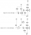
It's drawn with DipTrace, which is free for non-commercial use. I didn't have a 7404, but I tried it with a 4069, and it needed a pull-up resistor on pin 1.
 

Attachments

Last edited:

Thread Starter

Nicholas

Joined Mar 24, 2005
139
Hi again!

I've used that schematic, and it has worked great. However, when I add a 36V 10A
power supply, the coil energizes right away, and the MOSFET gets crazy hot right
away(I turn the power off right away)

How can this be? This is without any connection the controller, just the driver circuit.
The fet should be able to handle 36V and about 8A drawn, right?

I'm curious about how it can turn the mosfet on by itself

Thanks!
 

Thread Starter

Nicholas

Joined Mar 24, 2005
139
Sorry to bump this thread, I would rather make a new topic, but for some reason
the forum only lets me reply to old ones :)
 

Thread Starter

Nicholas

Joined Mar 24, 2005
139
Hi

It doesn't change anything. I made a small LED with a resistor to show when theres
a logic-level input present from the controller, and it lights up as soon as the power
supply is turned on.....this is without the controller connected. There must be some
kind of 'spill', feedback or whatever it's called. The LED lights up a lot, compared to
when an input form the controller is present
 

DC_Kid

Joined Feb 25, 2008
1,251
what type of diode in across that inductive coil? i typically double or triple zener off to ground to protect the fet (n+1 zeners where n is # to handle the dump power, +1 in case one fails). maybe your diode took a dump and then voltage spiked (aka flyback) and toasted your fet? using two diodes or two zeners helps when one of these discretes goes south... keep in mind you still get voltage climb on the D side of the coil when flyback occurs because the coil itself has Re.

i think you have to go verify that the fet is ok, and the emf diode is still good, etc.


btw, i would also isolate the gate signal circuit from the gate with a diode or opto-isolator. w/o isolation, if the gate signal clamps low when off then you are dumping gate charge back across a 10ohm load!!
 
Last edited:

Ron H

Joined Apr 14, 2005
7,063
Hi again!

I've used that schematic, and it has worked great. However, when I add a 36V 10A
power supply, the coil energizes right away, and the MOSFET gets crazy hot right
away(I turn the power off right away)

How can this be? This is without any connection the controller, just the driver circuit.
The fet should be able to handle 36V and about 8A drawn, right?

I'm curious about how it can turn the mosfet on by itself

Thanks!
You have to have something between the supply and the MOSFET that will limit the current. Something like a power resistor, or a solenoid, or a motor, etc. Don't count on the power supply voltage to drop to ≈0V when you turn on the MOSFET.
 

Ron H

Joined Apr 14, 2005
7,063
what type of diode in across that inductive coil? i typically double or triple zener off to ground to protect the fet (n+1 zeners where n is # to handle the dump power, +1 in case one fails). maybe your diode took a dump and then voltage spiked (aka flyback) and toasted your fet? using two diodes or two zeners helps when one of these discretes goes south... keep in mind you still get voltage climb on the D side of the coil when flyback occurs because the coil itself has Re.

i think you have to go verify that the fet is ok, and the emf diode is still good, etc.
All he needs is a 1N4001 across the coil, cathode to +V.


btw, i would also isolate the gate signal circuit from the gate with a diode or opto-isolator. w/o isolation, if the gate signal clamps low when off then you are dumping gate charge back across a 10ohm load!!
Huh?:confused::confused::confused:
 

DC_Kid

Joined Feb 25, 2008
1,251
gate of fet's hold charge. turn on then charge flows into the gate. turn off and charge flows out of the gate (this is a requirement for the fet to work right). if the control signal circuit connected to the gate is like a 555 then when the 555 goes low it's being connected to ground, hence gate charge can flow that path. put a diode to block that flow, etc.
 

Ron H

Joined Apr 14, 2005
7,063
gate of fet's hold charge. turn on then charge flows into the gate. turn off and charge flows out of the gate (this is a requirement for the fet to work right). if the control signal circuit connected to the gate is like a 555 then when the 555 goes low it's being connected to ground, hence gate charge can flow that path. put a diode to block that flow, etc.
Why do you think you should block that path? That's how you get fast turnoff. If you only have the resistor to ground for turn off, it will turn off next week.
 

DC_Kid

Joined Feb 25, 2008
1,251
wasnt sure what the use was. looks like that pull-down was for "off" state (albeit a tad high). not sure what the "controller" is, etc.
 

Ron H

Joined Apr 14, 2005
7,063
wasnt sure what the use was. looks like that pull-down was for "off" state (albeit a tad high). not sure what the "controller" is, etc.
The pulldown is there to keep the MOSFET off in case the input is floating, which can happen with microcontroller outputs, or if the MOSFET input is driven through a connector which can be disconnected.
 
Top