Facebook
 Google
 GitHub
 Linkedin

Hello,
I'm trying to build a high current MSFET switch to control the temperature of a 400 W heater bed. Instead of bying a board, i thought I would make one. I got following components from nearest store,
IRFZ48N and IRFZ48N MOSFET driver.
I have never used a MOSFET driver before and I'm little confused about the circuit
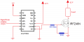
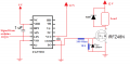
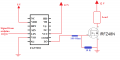
Following is the schematics of the circuit that I made. I haven't actually made the circuit in board since I don't know whether circuit is correct or not.
I have some general doubt about understanding the MOSFET data sheet. Load is 12 V 250 W heater. So current of 21 A.
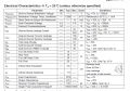
In the data sheet of IRFZ48, Gate threshold voltage is 2-4 V, that is the minimum volatge required to turn ON th channel, but it doesn't have enough channel width for 20 A, so I have to choose a gate voltage that is enough to create a channel for 20 A it should be less than maximum allowed Gate voltage, which 20 V from data sheet.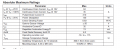
To know how much Gate current, I should check the output characteristics.
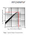
I have a 12 V supply, so giving a Vgs of 12 V will create enough channel.
Am I right up to this point? Is there any other general things that should consider for MOSFET switches??
Thanks
I'm trying to build a high current MSFET switch to control the temperature of a 400 W heater bed. Instead of bying a board, i thought I would make one. I got following components from nearest store,
IRFZ48N and IRFZ48N MOSFET driver.
I have never used a MOSFET driver before and I'm little confused about the circuit
Following is the schematics of the circuit that I made. I haven't actually made the circuit in board since I don't know whether circuit is correct or not.
I have some general doubt about understanding the MOSFET data sheet. Load is 12 V 250 W heater. So current of 21 A.
In the data sheet of IRFZ48, Gate threshold voltage is 2-4 V, that is the minimum volatge required to turn ON th channel, but it doesn't have enough channel width for 20 A, so I have to choose a gate voltage that is enough to create a channel for 20 A it should be less than maximum allowed Gate voltage, which 20 V from data sheet.
To know how much Gate current, I should check the output characteristics.
I have a 12 V supply, so giving a Vgs of 12 V will create enough channel.
Am I right up to this point? Is there any other general things that should consider for MOSFET switches??
Thanks