 Facebook
 Google
 GitHub
 Linkedin
Hello All,
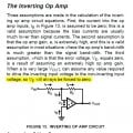
I would like to get some inputs on the inverting operational amplifier. I have attached picture (available on public domain) to put forth my questions.
1) With respect to inverting operational amplifier, how should Rf path be treated. Is it feedforward path from input to output? or it is feedback path from output to input? I am a little confused here ...
2) It is given that Ib current into the inverting pin of op-amp is very small (almost 0). Is this because the input resistance is very high?
3) If the real voltage gain is primarily due to resistances Rf and Rg then why the triangle symbol is called amplifier when the trick is due to these resistances?
4) By the term amplifier, does it mean that input shape will be maintained at output (with invertion) and higher amplitude?
Thanks a lot in advance ...
Attachments
-
 92.1 KB Views: 46
")


