Inverting a switch to short pads with a transistor

Thread Starter

Tanerinn

Joined Apr 28, 2020
3
I was the owner of a pair of Mackie CR3 speakers, until the PCB burnt through, and rather than tossing them out decided it would be worth a try to recycle them.

I bought the following items:

All good so far, except I'd like to reuse the switched volume knob on the Mackie speakers, which has two green LEDs behind it that illuminate when the speakers are turned on.

The switched pot is mounted on a small PCB, with the two LEDs in parallel, and connected in series to the switch. The switch is open when the volume knob is turned off, and closed when turned on.

The amplifier PCB has STBY and GND pads that, when shorted, will put the amp into standby mode:
stby pad.png

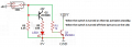
What I'd like is to have the volume knob switch be able to short these pads when the switch is open. The problem is that these two pads have less than 200 uA, which is the upper limit of the STBY pin on the TDA7498 IC, but I'd like to power the two LEDs that are next to the switch, too.

I have a 5 V and 1 A supply available from the SMPS (the amp is using the 24 V 4 A output) - is there a way with transistors that I could short the STBY and GND when the switch is open, and then when the switch is closed, "unshort" (I assume there's a word for this) the pads, and power the LEDs?

I don't know much about electronics, but will do my best to answer any questions!

Thanks in advance
 
Last edited:

Audioguru again

Joined Oct 21, 2019
6,691
The "woofers" are only 3" so what will you use to produce bass? Do you have a sub-woofer?
The Mackie CR3 produced 50W peak or 25W RMS but they do not say if it is total or per channel (12.5W per channel?).

The datasheet for the TDA7498 shows an output of 47W per channel at very high distortion into 8 ohm speakers with a 24V supply. If the speakers are 4 ohms then the speakers, the amplifier and the cheap Chinese power supply will blow up.

If you do not properly limit the LED currents then the LEDs will blow up.
 

MisterBill2

Joined Jan 23, 2018
18,477
IF you are able to put that amplifier system in standby by pulling down the standby connection with a simple NPN transistor, such as a 2N3904, then yes, it can be easily done. The transistor emitter to the common terminal, the collector to the standby terminal, the base to the +side of the LEDs in series with that switch. The other side of that to the common. Then add a pull-up resistor from the base to the +5 source, with the source negative to the common.
Now when the switch is off, (open), the +5 pulls up the transistor base, switching it on and pulling down the standby terminal. When the switch is ON, the pullup is bypassed and the transistor is off and the standby terminal goes high, however much that is.Probably the base will need to connect directly to the switch so that it gets pulled down enough to switch fully off. I hope this 1:30 AM explanation makes sense. The circuit is very simple and uses only 2 extra parts.
 

Thread Starter

Tanerinn

Joined Apr 28, 2020
3
The "woofers" are only 3" so what will you use to produce bass? Do you have a sub-woofer?
The Mackie CR3 produced 50W peak or 25W RMS but they do not say if it is total or per channel (12.5W per channel?).

The datasheet for the TDA7498 shows an output of 47W per channel at very high distortion into 8 ohm speakers with a 24V supply. If the speakers are 4 ohms then the speakers, the amplifier and the cheap Chinese power supply will blow up.

If you do not properly limit the LED currents then the LEDs will blow up.
They certainly aren't going to be putting out much bass, but it's enough for my needs. Thanks for the warning about the impedance. There doesn't seem to be much info from Mackie about the speakers, but I've been able to power them from this amplifier for several hours without blowing anything up yet - hopefully they're 6 or 8 ohm!

IF you are able to put that amplifier system in standby by pulling down the standby connection with a simple NPN transistor, such as a 2N3904, then yes, it can be easily done. The transistor emitter to the common terminal, the collector to the standby terminal, the base to the +side of the LEDs in series with that switch. The other side of that to the common. Then add a pull-up resistor from the base to the +5 source, with the source negative to the common.
Now when the switch is off, (open), the +5 pulls up the transistor base, switching it on and pulling down the standby terminal. When the switch is ON, the pullup is bypassed and the transistor is off and the standby terminal goes high, however much that is.Probably the base will need to connect directly to the switch so that it gets pulled down enough to switch fully off. I hope this 1:30 AM explanation makes sense. The circuit is very simple and uses only 2 extra parts.
Thanks for this description, it sounds like what I was hoping for! The problem for me is knowing what value of resistor to operate the transistor. Here's what I've got so far:

schematic.jpg

STBY and GND are the pads to short.
+5V and 0V are the second supply (5V 1A from the SMPS).

If the forward voltage of the LED is 2 V and I want 20 mA to power it, R1 should be (5 - 2) / 0.02 = 150 Ohms? Is a 150 Ohm resistor at R1 suitable for the transistor Q1?

Sorry for the questions but I'm very new to electronics, and when I see the datasheet for the 2N3904 I'm not sure what to look at. I also see a lot of people talking about saturating the transistor, but that means nothing to me!

Any further guidance would be greatly appreciated.
 

Audioguru again

Joined Oct 21, 2019
6,691
Your LED will never light up and the transistor will never turn off.
The datasheet for the 2N3904 and nearly every little NPN transistor shows that its base-emitter voltage is about 0.7v and it saturates (turns on well) when its base current is 1/10th its collector current.
With your 1k base resistor then the base current is (5V - 0.7V)/1k= 4.3mA but the switch is in series with the 2V LED that never gets 2V so the switch and LED do nothing.
With a 150 ohm base resistor then the base current is (5V - 0.8V)/150= 28mA which might blow up the base-emitter but again the LED never gets 2V so the switch and LED do nothing.

I made the circuit into an AND gate. The switch turns on the LED "AND" the transistor at the same time.
 

Attachments

MisterBill2

Joined Jan 23, 2018
18,477
Your LED will never light up and the transistor will never turn off.
The datasheet for the 2N3904 and nearly every little NPN transistor shows that its base-emitter voltage is about 0.7v and it saturates (turns on well) when its base current is 1/10th its collector current.
With your 1k base resistor then the base current is (5V - 0.7V)/1k= 4.3mA but the switch is in series with the 2V LED that never gets 2V so the switch and LED do nothing.
With a 150 ohm base resistor then the base current is (5V - 0.8V)/150= 28mA which might blow up the base-emitter but again the LED never gets 2V so the switch and LED do nothing.

I made the circuit into an AND gate. The switch turns on the LED "AND" the transistor at the same time.
Yes, the circuit shown here would work. But please know that I have used what were called :High Brightness" LEDs driven directly from CMOS gate outputs, with far less than 20 Ma and they lit up quite well.So some LED devices do not need the magic 20mA to lite up.
 

Audioguru again

Joined Oct 21, 2019
6,691
Some "high brightness" LEDs are simply dim ones in a case that focusses the light into a narrow beam. You can barely see them if they are not shining directly at you. Wide beam bright LEDs are good.
 

Thread Starter

Tanerinn

Joined Apr 28, 2020
3
Your LED will never light up and the transistor will never turn off.
The datasheet for the 2N3904 and nearly every little NPN transistor shows that its base-emitter voltage is about 0.7v and it saturates (turns on well) when its base current is 1/10th its collector current.
With your 1k base resistor then the base current is (5V - 0.7V)/1k= 4.3mA but the switch is in series with the 2V LED that never gets 2V so the switch and LED do nothing.
With a 150 ohm base resistor then the base current is (5V - 0.8V)/150= 28mA which might blow up the base-emitter but again the LED never gets 2V so the switch and LED do nothing.

I made the circuit into an AND gate. The switch turns on the LED "AND" the transistor at the same time.
Thank you for this! We're getting closer, but I think this isn't quite the behaviour that's needed. When the switch is closed, the LED should light up but the transistor should be "off". When the switch is open, the LED turns off and the transistor is "on", shorting STBY to GND.

Additionally, the LED and switched volume pot are already soldered on a small PCB, with the correct mounting setup for sitting flush against the front of the speaker cabinet:
1588815873662.png

A +ve wire goes to the anode of the LED, the cathode to one side of the switch, and the other side of the switch to the common wire.

Can this be made to work without inserting anything between the switch and the LED?
 
Top