It's unlikely to work properly on a breadboard . Wire inductance plus board capacitance are a recipe for spurious high-frequency oscillations, which in turn can result in excess current through the FETs and transformer. The IRF540 has significant gate capacitance which has to be charged up and discharged each cycle. The CD4047 can't source/sink enough current to do that quickly, and the complementary outputs of the CD4047 don't provide any dead-time, so there is a ~3uS period twice per cycle where both FETs are partly on at the same time. That results in a high current 'shoot-through', effectively shorting the 12V rail to ground.
It's possible one of the connections to one of the FETs isn't properly made, preventing a FET switching properly. That would cause a net DC current through the transformer and hence heating.
Thanks for the update, guess maybe I should transfer or solder the components on a Vero board. For the transformer I joined their source pin and send it to ground I.e the third pin reading from top, connect both of the drain pin I.e the center pin to the primary part of the transformer and also connected the gate pin ie the first pin to the irf540 Hope I Did the connection rightly.
But anyway, if you don't have an oscilloscope, slow down the frequency so that you can use LEDs in place of the transformer to verify the switching. If that works, speed it up until you can barely see flashing - this will be 50Hz or so - and see if the transformer works at this low frequency.
.................
But anyway, if you don't have an oscilloscope, slow down the frequency so that you can use LEDs in place of the transformer to verify the switching. If that works, speed it up until you can barely see flashing - this will be 50Hz or so - and see if the transformer works at this low frequency.
The transformer will saturate and overheat if the frequency is less than about 100Hz since it's a 9Vrms transformer and a squarewave has a large low frequency component generating the magnetizing current.
My simulations show that a ±12V, 91Hz square-wave generates about the same peak magnetizing current as a 9Vrms sinewave at 60Hz.
The DC voltage should be reduced to 9V if you want to operate the transformer at its rated mains frequency.
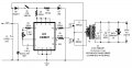
The schematic is stating "100 Watt inverter".
This can not be the case, as the transformer in the schematic is 18 Volts at 1.5 Amps = 27 Watt.
With some luck you will get about 20 Watts at the output, taking the losses in account.
hello house, this circuit is simple but I wonder y it refused to work... I even tried putting an led to replaced the transformer, nothing happened
..I then use my meter to test the output ie from the 4047 ic pin 11 is reading 2v while pin 10 reads 0v.. can anyone help...I really have little ideas on inverter making. Thanks
Is your powersupply 12 Volts?
Then the current in R3 (330 Ohm) will be (12 - 0.7 - 7.3) volts / 330 Ohms = 12 mA.
This is rather high.
What is the voltage across pin 7 and 14 when the gates of the fets are disconnected(pins 10 and 11)?
 Facebook
 Google
 GitHub
 Linkedin
 47.4 KB Views: 130
 . Wire inductance plus board capacitance are a recipe for spurious high-frequency oscillations, which in turn can result in excess current through the FETs and transformer. The IRF540 has significant gate capacitance which has to be charged up and discharged each cycle. The CD4047 can't source/sink enough current to do that quickly, and the complementary outputs of the CD4047 don't provide any dead-time, so there is a ~3uS period twice per cycle where both FETs are partly on at the same time. That results in a high current 'shoot-through', effectively shorting the 12V rail to ground.


