 Facebook
 Google
 GitHub
 Linkedin
Hello,
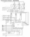
I attached two schematics.
My first question is about the schematic with the red and blue squares.
What does the transistor see in its collector when a low signal goes into the base?
My second question is about the blue square. You can see the other picture to realize that those pins are the emitters of the low transistors.
Can I remove those resistors and just plug the emitters to ground since I don't need to sense current?
Thank you.
Attachments
-
 74 KB Views: 31
 -
 36.3 KB Views: 27


