Interpreting Part Of A Schematic

Thread Starter

hihihi8

Joined Oct 4, 2017
10
hi guys & gals, first time here. I'm currently trying to build a guitar amp (Marshall MG10), and everything's going well except for the interpretation of a jack mono with single throw (jack mono on the schematic, but the part is a stereo one). Heres a picture2.PNG
4520.jpg 
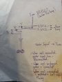
and the jack component
marshall-mg10-schematic-parts-big.jpg (and the full schematic, if it helps)
As you can see from the picture of the Jack component, there are 2 legs per segment of the connector, one that disconnects from the other when the connector is plugged in (the throw), and is the lead from the arrow.

I understand that the left-most rectangle is the ground/sleeve, and the indented lead to its right is the hot/tip, and that the 90 degree arrow-lead is the throw of the tip, but what i Don't understand is the 90 degree lead above the tip lead (Leading to R20). Is this the same as the throw? I don't see a connection dot, and the "X" of the arrow-lead says that its connected to nothing.

Any ideas guys?
PS: sorry if this question was dumb, i'm kinda new to this stuff..
 

Thread Starter

hihihi8

Joined Oct 4, 2017
10
Tip, ring, ground TRS. It looks like a resistive mixer to convert L/R audio from a stereo jack to a mono signal.
where would I connect the lead from R20? to the ring leg? (If this is to combine left and right from a TRS)

The TRS jack schematics ive seen in the past are usually like this 3.PNG
 

MrChips

Joined Oct 2, 2009
34,824
The schematic you have shown is for a mono instrument amplifier (Marshall MG10 guitar amp).
When nothing is plugged into the MP3 input jack, the signal is from the guitar preamp stages.
Why you plug into the MP3 jack, the signal from the guitar preamp is disconnected. Only the Left Channel of your MP3 source (Tip) is fed into the MP3 input.

What you really need is a stereo-to-mono adapter before plugging into the MP3 input.

Take two 100Ω resistors and a stereo MP3 jack. Connect one resistor to the Tip. Connect the second resistor to Ring. Join the other ends of the resistor. Connect sleeve to sleeve of a MP3 mono plug. Connect the joined connection to the Tip of your MP3 mono plug going into the Marshall amp.
 

Dodgydave

Joined Jun 22, 2012
11,395
Your full circuit shows a Stereo socket for Mp3 input, both Left and Right channels are used and are mixed together using R20/21 resistors to make a Mono signal..
 

ebeowulf17

Joined Aug 12, 2014
3,307
Your full circuit shows a Stereo socket for Mp3 input, both Left and Right channels are used and are mixed together using R20/21 resistors to make a Mono signal..
Where do you see that? On the full schematic I only see the same thing as in the cropped, zoomed image. Looks to me like a mono jack.
 

Thread Starter

hihihi8

Joined Oct 4, 2017
10
after some thinking, i believe the schematic isn't the most well drawn:

in pictures of this guitar amp's PCB (https://www.electrosmash.com/images/tech/mg10/marshall-mg10-pcb-1000.png), one can clearly see that the mp3 input and headphones output jacks are stereos with throws on all legs (left two).

what would make sense logically is: the line coming from guitar's preamp (the lead leading to R22) should be connected to the throw of the tip or ring of the TRS jack, with the corresponding leg connected to the power amplifier. This way, when the mp3 input is Disconnected, the guitar preamp's signal passes through the throw and one of the 3.3k ohm resistors into the power amplifier section. In the case that mp3 input is Connected, the throw (guitar preamp) is disconnected, preventing signal from passing backwards. In this case, both left and right are connected and pass through the two 3.3k resistors acting as resistive audio mixers before going into the power amplification stage.

IMG_20171005_185945.jpg

Just my interpretation, feel free to correct me if i'm wrong (or show agreement, I need to be relatively sure, since i'm building this)

TLDR: schematic drawn badly. Section acts as resistive audio mixer + guitar preamp disconnection throw.
 

Attachments

Top