Interfacing with numeric keypad and seven segment display

Thread Starter

74266

Joined Mar 20, 2016
41
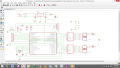
I am planning to make a code where after you push two numbers in numeric keypad and press the # button it will start to decrements until it will
stop to 0

I will assign:
RD as the output of 2 seven segment(is will 2 7447 IC decoder)
RA[0-3] as the row input of keypad
RB[0-2] as the column input of keypad

upload_2016-10-2_19-5-36.png
---------------------- -------------------------
What I dont know is what will be the benefit on using RB change interrupt
 
Last edited:

djsfantasi

Joined Apr 11, 2010
9,163
Decrement from where?

For example, if you need to press the keypad while decrementing or doing something else, the interrupt method will allow you to continue processing while not missing a key press.

What is this code going to be implemented on? PIC? Pi? Arduino? AVR?
 

Thread Starter

74266

Joined Mar 20, 2016
41
Decrement from where?

For example, if you need to press the keypad while decrementing or doing something else, the interrupt method will allow you to continue processing while not missing a key press.

What is this code going to be implemented on? PIC? Pi? Arduino? AVR?
In Pic and Assembly code
Also what I am saying in decrement is that if I press [9] then I press [1] what it will display is 91 then if you press # button it will decrement from
91 until it reaches 00
 

JohnInTX

Joined Jun 26, 2012
4,787
This thread has an example of how to do a keypad/display with a PIC. There are others here that you can find by searching the forum.
http://forum.allaboutcircuits.com/t...nt-display-using-8051-microcontroller.100549/

I would not use interrupt on change for basic scanning. Instead, create a timer interrupt that scans the keypad and emits valid key codes. The basic process in the timer interrupt service routine is:
For N rows
Turn on a row and see if any keys aim the column are pressed.
If not,do the next row.
When you find a key pressed, scan a few more times to validate the key (debounce).
When satisfied, combine the row and column numbers to get a unique key code - it doesn't have to match the legend on the key yet. For example, key 3 (11 in binary) on row 1 (01) could combine to code 1101 ( key code 13)
Store the key code end set a flag to indicate a new key.
Continue scanning the matrix until no keys are pressed, indicating the key is released.
Resume scanning for the next key.

In your main code, poll the flag to look for new keys emitted by the keypad scanner. When the flag is set, read the key code and clear the flag for the next key. Decode the key code directly or use a lookup table to translate key the key code to a suitable character. Process the keys as desired. For example 0-9 go into the preset, #starts the countdown etc.

The main points are to scan the keypad with its own little engine and make it emit valid key codes separately from the processing. You can add a translation table between the scanner and the processor to make things easier to manage. Many keypads use some variation on this technique.

Display multiplexing is frequently timed by the same interrupt and sometimes shares hardware segments driven by the row lines, etc. That's more complex but doable. There are lots of display multiplexing examples here - search away. I mux LEDs using a timer interrupt as well; The main routine stores the digits to display. The digit values are used as an index into a table of segment patterns. The pattern for the current digit gets fetched up, written to the port and the digit gets turned on. Next interrupt, next digit and so on.

This sort of rat of thing isn't trivial for the beginner but by breaking it into small functional blocks becomes manageable and learnable.

Good luck!
 
Last edited:

Thread Starter

74266

Joined Mar 20, 2016
41
THIS is the code I made but when use it in my dev board it is not showing any output
Code:
    #include "P18F4550.inc"
   
    config  FOSC = HS       
    config  CPUDIV = OSC1_PLL2
    config  PLLDIV = 1
    config  PWRT = OFF
    config  BOR = OFF
    config  WDT = OFF
    config  MCLRE = ON
    config  STVREN = ON
    config  LVP = OFF
    config  ICPRT = OFF
    config  XINST = OFF
    config  DEBUG = OFF
    config  FCMEN = OFF
    config  IESO = OFF
    config  LPT1OSC = OFF
    config  CCP2MX = ON
    config  PBADEN = OFF
    config  USBDIV = 2
    config  VREGEN = OFF
   
    WHAT_BUTTON equ 0x000
    OUTPUT    equ 0x001  
    COLUMN    equ 0x002
    OPERATOR    equ 0x003
    SEGMENT     equ 0x004
    TEMP        equ 0x005
    ZERO        equ 0x006
    W_TEMP      equ 0x007
    S_TEMP      equ 0x008
   
    org 0x0000
    BRA START
   
    org 0x0008
    BRA HISR

   
    org 0x0018
    BRA LISR

   
START
    ; Disable Analog Comparators multiplexed with RA & RB
    MOVLW 0x0F
    MOVWF ADCON1, ACCESS
    MOVLW 0x07
    MOVWF CMCON, ACCESS


SETUP   
    CLRF ZERO,ACCESS
    CLRF WHAT_BUTTON, ACCESS
    CLRF OUTPUT, ACCESS
    ; Set the direction of RA[0-3] to INPUT;
    MOVLW 0x0F
    MOVWF TRISA, ACCESS
     ; Set the direction of RB[0-2] to INPUT;
    MOVLW 0x07
    MOVWF TRISB, ACCESS
   
    ; Set the direction of RD[0-7] to OUTPUT
    CLRF TRISD, ACCESS


;INT0 & INT1 & INT2 :LOW PRIORITY
;TIMER0:HIGH PRIORITY
   
   
;FOR INT0-COLUMN3
    BCF INTCON, INT0IF, ACCESS
    BSF INTCON, INT0IE, ACCESS
    BCF INTCON2, INTEDG0, ACCESS
;FOR INT1-COLUMN2    
    BCF INTCON3, INT1IF, ACCESS
    BSF INTCON3, INT1IE, ACCESS
    BCF INTCON3, INT1IP, ACCESS
    BCF INTCON2, INTEDG1, ACCESS
;FOR INT2-COLUMN1
    BCF INTCON3, INT2IF, ACCESS
    BSF INTCON3, INT2IE, ACCESS
    BCF INTCON3, INT2IP, ACCESS
    BCF INTCON2, INTEDG2, ACCESS
;FOR INT   
    BSF RCON, IPEN, ACCESS
    BSF INTCON, GIEH, ACCESS
    BSF INTCON, GIEL, ACCESS
    BSF INTCON, RBIE, ACCESS
    BCF INTCON, RBIF, ACCESS
   
; INTERRUPT - TMR0
    BCF INTCON, TMR0IF, ACCESS
    BSF INTCON2, TMR0IP, ACCESS
    BSF INTCON, TMR0IE, ACCESS


; TMR0
    MOVLW 0xFA
    MOVWF TMR0H, ACCESS
    MOVLW 0xE9
    MOVWF TMR0L, ACCESS
    MOVLW 0x87            ; 16BIT: 1:256 PRESCALER; INTERNAL CLOCK
    MOVWF T0CON, ACCESS
   
MAIN
    BTFSC COLUMN,0x2,ACCESS
    BRA COLUMN_2
    BTFSC COLUMN,0x1,ACCESS
    BRA COLUMN_1
    BTFSC COLUMN,0x0,ACCESS
    BRA COLUMN_0
   
   
COLUMN_2
    BTFSC PORTA, 0x0, ACCESS       
    MOVLW 0x03                ;'00000001' - NUM3   
    BTFSC PORTA, 0x1, ACCESS       
    MOVLW 0x06                ;'00000100' - NUM6
    BTFSC PORTA, 0x2, ACCESS           
    MOVLW 0x09                ;'00000111' - NUM9   
    BTFSC PORTA, 0x3, ACCESS           
    BTG OPERATOR, 0x0, ACCESS        ;'00000111' - NUM#   
    BRA DISPLAY

COLUMN_1
    BTFSC PORTA, 0x0, ACCESS       
    MOVLW 0x02                ;'00000010' - NUM2   
    BTFSC PORTA, 0x1, ACCESS       
    MOVLW 0x05                ;'00000101' - NUM5
    BTFSC PORTA, 0x2, ACCESS           
    MOVLW 0x08                ;'00001000' - NUM8   
    BTFSC PORTA, 0x3, ACCESS           
    MOVLW 0x00                ;'00000000' - NUM0   
    BRA DISPLAY
COLUMN_0   
    BTFSC PORTA, 0x0, ACCESS       
    MOVLW 0x01                ;'00000001' -NUM1   
    BTFSC PORTA, 0x1, ACCESS       
    MOVLW 0x04                ;'00000100' -NUM4
    BTFSC PORTA, 0x2, ACCESS           
    MOVLW 0x07                ;'00000111' -NUM7   
    BRA DISPLAY
   
DISPLAY
    ;INT2 - COLUMN_0
    ;INT1 - COLUMN_1
    ;INT0 _ COLUMN_2
    MOVWF WHAT_BUTTON,ACCESS
    MOVF OUTPUT,W,ACCESS
    MOVWF TEMP,ACCESS
    BTFSC SEGMENT,0x0,ACCESS
    SWAPF TEMP,W,ACCESS
    BTFSC SEGMENT,0x1,ACCESS
    IORWF OUTPUT,W,ACCESS
    BTFSC OPERATOR,0x0,ACCESS
    BRA START_DEC
    MOVWF LATD, ACCESS
   
START_DEC
    MOVF ZERO,W,ACCESS
    CPFSGT OUTPUT,ACCESS
    BRA MAIN
    MOVWF LATD,ACCESS    
    BRA MAIN  
   
INT0_ISR
    BTG SEGMENT,0x0,ACCESS
    BTG COLUMN, 0x0, ACCESS
    BCF INTCON, RBIF, ACCESS
    BCF INTCON, INT0IF, ACCESS
    RETURN

INT1_ISR
    BTG SEGMENT,0x0,ACCESS
    BTG COLUMN,0x1,ACCESS
    BCF INTCON, RBIF, ACCESS
    BCF INTCON3, INT1IF, ACCESS
    RETURN

INT2_ISR
    BTG SEGMENT,0x0,ACCESS
    BTG COLUMN,0x2,ACCESS
    BCF INTCON, RBIF, ACCESS
    BCF INTCON3, INT2IF, ACCESS
    RETURN

   
LISR
    BTFSC INTCON, INT0IF, ACCESS
    RCALL INT0_ISR
    BTFSC INTCON3, INT1IF, ACCESS
    RCALL INT1_ISR
    BTFSC INTCON3, INT2IF, ACCESS
    RCALL INT2_ISR
    RETFIE FAST   
   
HISR  
    BTFSC INTCON, TMR0IF, ACCESS
    RCALL TMR0_ISR
 

    RETFIE      
   
TMR0_ISR
    BTFSC OPERATOR, 0x0, ACCESS
    DECF OUTPUT,F,ACCESS
    BCF INTCON, TMR0IF, ACCESS
    RETURN

   
end                            ;    We always need to have end at the end, even if we don't want the program
this is the schematic I use in my dev board
upload_2016-10-5_14-11-19.png
 

Attachments

Top