Interfacing problem -capacitive moisture sensor

Thread Starter

shibin_varghese

Joined Jan 14, 2019
73
Hi all
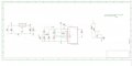
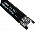
I am trying to interface a capacitive moisture sensor with a controller. Since the controller is far away from the sensor we use a 4-20mA voltage to current converter. Initially, a resistive sensor was used and is working fine. But the circuit is not working when I switched to a capacitive sensor. The output of the sensor is 1.6V to 2.8V. I think the output current of the sensor is very low. Is there any method to amplify the current linearly without changing the voltage.
 

Attachments

Thread Starter

shibin_varghese

Joined Jan 14, 2019
73
No, I don't have one.
I think the problem is with the low output current. is there any method to amplify the current keeping the voltage level the same as from the sensor.
 

pmd34

Joined Feb 22, 2014
527
Hi shibin, from what I found online:
https://www.dfrobot.com/wiki/index.php/Capacitive_Soil_Moisture_Sensor_SKU:SEN0193
The sensor you have uses a TLC555 to send out a PWM signal that is then converted to a simple DC voltage level with a resistor and capacitor. (Its a simple form a Digital to analog conversion.)

You could move the resistor / capacitor filter to your receiver board, so transmit the pulsed signal instead which would be more robust.
You could actually also simply measure the frequency of this signal directly with your microcontroller.
 

Ya’akov

Joined Jan 27, 2019
9,071
hi shibin,
Welcome to AAC
Do you have a datasheet for the cap sensor that you could post.?
E
According to the very incomplete datasheet for this design (sold by a few vendors) the output is 5ma.

But “doesn’t work” isn’t really enough information. It would be nice to have empirical measurements at the sensor, at the output of the current loop, and, of course to know just how far away and what sort of wire is connecting them.
 

Thread Starter

shibin_varghese

Joined Jan 14, 2019
73
Here is the circuit diagram of the sensor.
The 555 timer creates a constant frequency and the RC filter following the 555 performs the sensing function. C is the sensor.
As the C changes based on the moisture content in the soil. The output voltage changes.
The industrial standard is 4-20mA. We need to convert the output to that.
 

Attachments

Ya’akov

Joined Jan 27, 2019
9,071
You could move the resistor / capacitor filter to your receiver board, so transmit the pulsed signal instead which would be more robust.
You could actually also simply measure the frequency of this signal directly with your microcontroller.
I would also make sure that it is wired correctly, and that the connection is not so long and thin the voltage drop makes it fail. The first problem was it didn’t work so a current converter was added hoping to fix it now we are fixing the current converter but that’s a second order fix. Confirming the first assumption would be good.
 

Thread Starter

shibin_varghese

Joined Jan 14, 2019
73
According to the very incomplete datasheet for this design (sold by a few vendors) the output is 5ma.

But “doesn’t work” isn’t really enough information. It would be nice to have empirical measurements at the sensor, at the output of the current loop, and, of course to know just how far away and what sort of wire is connecting them.
When the voltage is transmitted over a large distance through a wire, it causes a voltage drop. That's why we converted it into a current signal.
4-20mA is the industrial standard for analog sensors.
 

Thread Starter

shibin_varghese

Joined Jan 14, 2019
73
I would also make sure that it is wired correctly, and that the connection is not so long and thin the voltage drop makes it fail. The first problem was it didn’t work so a current converter was added hoping to fix it now we are fixing the current converter but that’s a second order fix. Confirming the first assumption would be good.
The output of the sensor is between 1.5V- 2.8V.
The current to voltage converter is working fine if we vary its input.
But it is not working when it is connected to the sensor because its output current is very low. Is there any method to amplify the current keeping voltage same as from the sensor
 

ericgibbs

Joined Jan 29, 2010
18,766
I think the output current of the sensor is very low. Is there any method to amplify the current linearly without changing the voltage.
hi shibin,
It is possible to 'amplify' the current and still keep the voltage profile.
What level of current do you require.?
E

EDIT:
web example.
BOPA1_LTspice1.JPG
 

Ya’akov

Joined Jan 27, 2019
9,071
The output of the sensor is between 1.5V- 2.8V.
The current to voltage converter is working fine if we vary its input.
But it is not working when it is connected to the sensor because its output current is very low. Is there any method to amplify the current keeping voltage same as from the sensor
Someone asked to see the schematic for your amplifier. That would help. 5ma should be enough current. Is the input impedance to the amplifier very low?
 

Thread Starter

shibin_varghese

Joined Jan 14, 2019
73
hi shibin,
It is possible to 'amplify' the current and still keep the voltage profile.
What level of current do you require.?
E
The input current is in the range of 0-5 mA and the voltage level is 1.5- 2.8V. The output we require is in the range at the range of 10mA
 

Ya’akov

Joined Jan 27, 2019
9,071
Here it is
Well, current amplifiers are not very hard, but I can’t help thinking something else is going on here. That chip is designed to deal with voltage on the input and 10mA seems like a lot of power at the input voltage to require.

In any case, @ericgibbs example from the web shows the idea. There are many current amplifier sources on the web, not hard to find. It may be a solution but be sure you haven’t missed anything.

It’s not going to be an input impedance problem because that chip uses opamp input. But do make sure R14 is correct.
 

Thread Starter

shibin_varghese

Joined Jan 14, 2019
73
Well, current amplifiers are not very hard, but I can’t help thinking something else is going on here. That chip is designed to deal with voltage on the input and 10mA seems like a lot of power at the input voltage to require.

In any case, @ericgibbs example from the web shows the idea. There are many current amplifier sources on the web, not hard to find. It may be a solution but be sure you haven’t missed anything.

It’s not going to be an input impedance problem because that chip uses opamp input. But do make sure R14 is correct.
The current to voltage converter is working fine. When I varied the input from a variable power supply it did give an output of 4-20mA.
But the problem is when it is connected with the sensor. It because the output current of the sensor is not enough to mark. That's why we are looking for a current amplifier keeping the voltage profile the same.
 

Ya’akov

Joined Jan 27, 2019
9,071
The current to voltage converter is working fine. When I varied the input from a variable power supply it did give an output of 4-20mA.
But the problem is when it is connected with the sensor. It because the output current of the sensor is not enough to mark. That's why we are looking for a current amplifier keeping the voltage profile the same.
Yes I understood your assertion. What I don't know is how you determined the current wasn't enough. While checking with a power supply is helpful, how did that show the current from the sensor was the problem? It shows that something about the sensor is not working with the converter, but how did you work out it was the current?
 

Ya’akov

Joined Jan 27, 2019
9,071
The current to voltage converter is working fine. When I varied the input from a variable power supply it did give an output of 4-20mA.
But the problem is when it is connected with the sensor. It because the output current of the sensor is not enough to mark. That's why we are looking for a current amplifier keeping the voltage profile the same.
I don’t mean to frustrate you but with the information you’ve provided it is hard to tell if a current amp is actually a solution to the problem, and current amplifier information is everywhere, even in older AAC threads.

Try looking for opamps as current amplifiers. You will find practical circuits.
 
Top