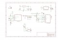
Interfacing problem -capacitive moisture sensor

Thread Starter

shibin_varghese

Joined Jan 14, 2019
73
Yes I understood your assertion. What I don't know is how you determined the current wasn't enough. While checking with a power supply is helpful, how did that show the current from the sensor was the problem? It shows that something about the sensor is not working with the converter, but how did you work out it was the current?
The only chance is the lack of current from the sensor. If not what could be the possible reason
 

Ya’akov

Joined Jan 27, 2019
10,259
The only chance is the lack of current from the sensor. If not what could be the possible reason
Well, I don’t know. Did you confirm this somehow, or did you assume that everything else was being held constant?

Did you measure the current from the sensor?

I am not there, but as I said, you probably don’t need any help working out how to use an o-amp as a current amplifier, or if you do, start and when you have questions, ask those.
 

Alec_t

Joined Sep 17, 2013
15,120
Why aren't you feeding the output of the sensor directly to the input (pin 6) of the V-to-I converter IC, instead of loading it down with all those resistors?
 

ericgibbs

Joined Jan 29, 2010
21,463
Why aren't you feeding the output of the sensor directly to the input (pin 6) of the V-to-I converter IC, instead of loading it down with all those resistors?
Hi alec,
Is that for me to read.?
If so they are just dummy values to show the current plot.
E
 

MrChips

Joined Oct 2, 2009
34,887
Take a look at the design of the sensor circuit.
In uses a TLC555 timer circuit to generate a 3V PWM digital signal.
Remove C3 and short across D1. Just measure the PWM signal directly from the 555-timer output using a timer module on your MCU.

SEN0193 Capacitive Sensor.jpg
 
Top