Interfacing inductive movement sensor (a bolt inside a coil moving up&down)

Thread Starter

Thomas Prüfer

Joined Nov 22, 2017
28
Hi,

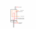
I am missing an idea how to get distance values out of a sensor which is a single coil with a steel bolt inside which is moving while position is changed. I need to get linear values which I can feed into an analog input of a Teensy which then will convert this values and send it on a CAN bus like network (NMEA2K)

Since this sensors are without any description it is hard to find out what kind of preferendes those have. What I know is that it is a coil with to wires so I guess the whoe thing is based on inductance.

How can I design the cirquit to interface inductive sensors to feed the analog 3.3 V inputs? I was reading a lot and came on LVDT so I bought some LM339 already but still unsure how to do this as simple as possible.
This sensors shel give back the position of tabs moving slowly up and down.

Attached a drawing.

THX for help!
 

Attachments

Last edited:

Vinnie90

Joined Jul 7, 2016
86
If you have an oscilloscope you could try to hook up your sensor and look at the signal while you move it. It is hard to design something without any information for example about the bandwidth or voltage level coming out of the sensor.

Most likely since your sensor has two wires only you could use a differential amplifier to measure the voltage and do a sort of calibration (since you have no datasheet). The LM339 are comparators so not very useful if you want an analog output.
 

BobTPH

Joined Jun 5, 2013
8,804
If I understand the problem correctly, you are going to try to measure the position of the bolt, not movement of the bolt, correct?

If so, then they way to do it is measure the inductance of the coil. As the bolt moves in, the inductance will increase. You then need to calibrate the inductance to position function.

Bob
 

Thread Starter

Thomas Prüfer

Joined Nov 22, 2017
28
@vinni
There is nothing to measure yet, to cables are comming out of the coil and are not connected to any power supply yet.

@BobTPH
I would like to measure the position of the bolt inside the coil. The bolt is longer than the whole coil and is entering the coil from the lower side. While moving the bolt is traveling upwards inside the coil with the lower end still outside of the coil.

@ci139

Top, what a help! And of course already visited. By the way, LVDT's are different.
 

Vinnie90

Joined Jul 7, 2016
86
There is nothing to measure yet, to cables are comming out of the coil and are not connected to any power supply yet.
It works differently than what I thought. What still puzzles me is that you only have 2 wires out when you should have 4.

For the readout I'm still convinced that the LM339 are not suitable in your case, because it is a comparator (it compares the voltage difference at the inout pins and the output is negative or positive rail if the difference is positive or negative). To have an analog output you need most likely a differential amplifier.
 

TeeKay6

Joined Apr 20, 2019
573
It works differently than what I thought. What still puzzles me is that you only have 2 wires out when you should have 4.

For the readout I'm still convinced that the LM339 are not suitable in your case, because it is a comparator (it compares the voltage difference at the inout pins and the output is negative or positive rail if the difference is positive or negative). To have an analog output you need most likely a differential amplifier.
@Thomas Prüfer
As I understand you: You have a coil and a bolt that is longer than the coil. Thus as it moves the position of the bolt can vary from entirely outside the coil to completely filling the coil (with excess bolt still remaining outside the coil). The inductance of the coil will vary as the bolt is inserted from a lower value to a high value. The lower value will not be 0.0 H. The difference between the lower and upper values will depend on the coil and bolt dimensions and on the type of steel of which the bolt is made. If the coil is driven by a constant AC voltage, the current through the coil will vary as the inductance varies. The graph of inductance vs insertion depth will likely be rather non-linear, although it may be linear over a portion of the travel. The current flowing through the inductance will therefore vary in like manner to the inductance, from a maximum current (min inductance) to a minimum current (max inductance). If the current is measured, it would give a rough estimate of inductance, and thus of bolt position. Is this what you have in mind?
 

Thread Starter

Thomas Prüfer

Joined Nov 22, 2017
28
@TeeKay6

You are almost right. Just that there is now voltage attaced to the bold. the bolt is in the middle of a hydraulic cylinder surounded by the coil.
I tried to make a drawing. May this describes better the problem.
 

Attachments

Sensacell

Joined Jun 19, 2012
3,432
You will need to make the coil a frequency-determining part of an oscillator.
Measure the change in frequency as the bolt moves.

It's not going to be very linear.
 

Reloadron

Joined Jan 15, 2015
7,501
How much travel will the rod or in this case bolt have? While I can't provide exact numbers or specific hardware I can make a suggestion. You can as mentioned use the inductor with a slug passing into it and as the inductance changes so would go the frequency of an oscillator built around it. Pass that to a F/V (Frequency to Voltage) converter and measure the voltage which should be proportional to the rod position, just not very linear.

The next is a commonly used method but involves several coils and four wires. It's called an Analog Rod Position Indicator system or an IRPI. A Google of IRPI will get you some notes like this one which illustrates how it works. This is complex but as can be seen in the link is suitable for long travel distances.

Again knowing the expected travel is important. When conditions allow then using a simple Linear Position Transducer similar to the link can be employed. The linear position transducer is likely the simplest to use. I have used them to accurately measure distances of 0.5" to 6.0". Again it depends on what your hardware configuration will allow. Nice thing is a simple connection to your micro-controller and easily calibrated in your code. I also would not rule out a string pot or commonly called YoYo Pot.

Most of this depends on your hardware configuration and the required travel along with how fast the sensor must respond. Depending on your budgetary constraints there are also some very accurate LASER systems.

Ron


TeeKay6

Joined Apr 20, 2019
573
@TeeKay6

You are almost right. Just that there is now voltage attaced to the bold. the bolt is in the middle of a hydraulic cylinder surounded by the coil.
I tried to make a drawing. May this describes better the problem.
@Thomas Prüfer
As I understand your initial post, the sensor already exists; you are not looking for ideas on how to measure the position of the bolt. You are looking for ideas on how to read the existing sensor(s). Is this correct?
 

Thread Starter

Thomas Prüfer

Joined Nov 22, 2017
28
@Reloadron
@TeeKay6

Thanks for the informations! The travel is about 100 mm max. Maybe 1-3 cm +-
In case of 100 mm travel 1 mm makes a lot change to the trim tabs. Will say that an accuracy of 1% (1mm) would be great to have.

I'd like to use the Teensy 3.2 or Teensy 4.0 Microcontroler for this application. By that I can translate the analog value then simple to the CAN bus protocol which I need to desplay the data correct on the MFD.

BUT, regarding the accuracy, standart devices show the positions by LED from 1 - 10. Which will be an accuracy of 10%. Since I would like to automate the Trim tabs later I would need a better accuracy then 10%.

So what I axactly need is the cirquit to get a 0-3.3 voltage to reed this by the microcontroler.
 

TeeKay6

Joined Apr 20, 2019
573
@Reloadron
@TeeKay6

Thanks for the informations! The travel is about 100 mm max. Maybe 1-3 cm +-
In case of 100 mm travel 1 mm makes a lot change to the trim tabs. Will say that an accuracy of 1% (1mm) would be great to have.

I'd like to use the Teensy 3.2 or Teensy 4.0 Microcontroler for this application. By that I can translate the analog value then simple to the CAN bus protocol which I need to desplay the data correct on the MFD.

BUT, regarding the accuracy, standart devices show the positions by LED from 1 - 10. Which will be an accuracy of 10%. Since I would like to automate the Trim tabs later I would need a better accuracy then 10%.

So what I axactly need is the cirquit to get a 0-3.3 voltage to reed this by the microcontroler.
@Thomas Prüfer
No one can answer your question with the information provided thus far. We do not know the coil resistance, inductance, or resonant frequency (for at least the cases when the bolt is fully out and fully into the coil). We do not know how much the inductance varies with bolt position. We do not know what would be an appropriate frequency of excitation for the coil. We cannot say how linear the output would be; that depends on bolt and coil characteristics you are likely unable to give (e.g. uniformity of magnetic characteristics of the bolt along its length; uniformity of winding of the coil). In summary, many measurements need to be made before a reliable attempt at a circuit could be made.
 

Thread Starter

Thomas Prüfer

Joined Nov 22, 2017
28
@TeeKay6

You sound almost angry.. ;-) look at the picture attached. No more information available. The indictors are mounted under the waterline. So not so easy with 5 tonn of boat to take them apart to check details. There no information provided by the producer even. I send them some quetions regarding the details but they can't or didn't wanted to answer.

How ever, I didn't expected to get a full developed cirquit of you guys, really not. I am looking for ideas what could be the solution. Then more try and error to finally come toa result which will be usable.

So the coil is cast in platic, not even visible.

Actually what I am trying to do is backward engeneering of this device since the small electronic where the sensors should be connected to is exactly doing what I try to build. There just one thing why I can not use the one which is delivered in this set. Calibration! To calibrate the sensors I would need a multifunction display from Lowrance which costs aboutt 2T usd. This cal. needs to be done just once initially before the device is starting to send the information to the NMEA2K bus. The poin is that I am using a different (from y view much better) Navigaation device from Raymarine which have also costs 2.5K usd. So you may understand my problem, spent 2K for one 5 minute ontime job?!

I have build this device for other sensors already, working just fine. The only thing I have problem with that I do not know how to interface a coil with a moving bolt inside to provide a analog voltage.

May the idea from BobTPH is not so bad. The frequency I could then tranform to voltage using a LM2907 or 2917 (used before for engine RPM).
 

Attachments

TeeKay6

Joined Apr 20, 2019
573
@TeeKay6

You sound almost angry.. ;-) look at the picture attached. No more information available. The indictors are mounted under the waterline. So not so easy with 5 tonn of boat to take them apart to check details. There no information provided by the producer even. I send them some quetions regarding the details but they can't or didn't wanted to answer.

How ever, I didn't expected to get a full developed cirquit of you guys, really not. I am looking for ideas what could be the solution. Then more try and error to finally come toa result which will be usable.

So the coil is cast in platic, not even visible.

Actually what I am trying to do is backward engeneering of this device since the small electronic where the sensors should be connected to is exactly doing what I try to build. There just one thing why I can not use the one which is delivered in this set. Calibration! To calibrate the sensors I would need a multifunction display from Lowrance which costs aboutt 2T usd. This cal. needs to be done just once initially before the device is starting to send the information to the NMEA2K bus. The poin is that I am using a different (from y view much better) Navigaation device from Raymarine which have also costs 2.5K usd. So you may understand my problem, spent 2K for one 5 minute ontime job?!

I have build this device for other sensors already, working just fine. The only thing I have problem with that I do not know how to interface a coil with a moving bolt inside to provide a analog voltage.

May the idea from BobTPH is not so bad. The frequency I could then tranform to voltage using a LM2907 or 2917 (used before for engine RPM).
@Thomas Prüfer
I am not in the least angry. However, I do not believe that you understand the difficulty in giving you a useful answer with the little info we have.
 

BobTPH

Joined Jun 5, 2013
8,804
OK, I assumed you would know how to get from the frequency to the voltage, but apparently you do not.

To do this with an analog circuit would be a nightmare. You need a microcontroller to read the frequency, apply a function determined by calibration, and output a voltage by using a DAC or PWM with a low pass filter.

Does this help?

If you are looking for a simple answer, I don’t think there is one.

Bob
 

Reloadron

Joined Jan 15, 2015
7,501
OK, you have a few things here which will be a problem. Going back to the image in your first post they show the bolt, we can call it a bolt, moving in and out of a coil so yes, two wires out. A best guess here is that, as mentioned, the inductance of the coil will change as an iron core, the bolt, is moved in and out. Back to this later.

You mentioned "trim" and also a boat came up along with underwater. So what you have is a boat with trim tabs and the idea here is to know the position of those tabs in the pilot house or simply put drivers seat. The trim is set depending on water conditions, weight on the boat and weight distribution on the boat. The trim tabs move on an axis so we can say X number of degrees of trim or express the trim as a percentage such as 0 to 100% trim. Now earlier you mentioned:
BUT, regarding the accuracy, standart devices show the positions by LED from 1 - 10. Which will be an accuracy of 10%. Since I would like to automate the Trim tabs later I would need a better accuracy then 10%.
First thing to understand with this would be that is not accuracy but rather the resolution. Resolution, in simple terms can be defined as the ability to read an instrument or of an instrument to be read. In this case with a 10 LED display each LED represents 10% of trim. So the best we can resolve is 10% increments of change. Accuracy is a qualitative term, the degree to which the result of a measurement, calculation, or specification conforms to the correct value or a standard. Ideally we want accuracy with a high resolution.

It would be helpful to know how the LED display is driven. Setups like this are normally driven with a voltage level fed into a simple chip like the LM3914 Dot/Bar Display Driver. With what you mention they are getting a signal somehow. Since they offer a position display like this there is a good possibility the signal from the cylinder is as good as it gets. Meaning the accuracy of the signal to work with will only afford a trim position to a given degree of accuracy or uncertainty, allowable error.

The only way to start is knowing what the inductance of those two wires actually is. Find the cable from the trim tab, locate those two wires and using a LCR Meter (Meter to measure inductance) measure the inductance with zero trim and 100% trim. Then as mentioned build an oscillator circuit around that. The oscillator out is fed into a F/V (Frequency to Voltage) converter and scaled as 0 to 100 percent in your code. This is not a simple task or design to just wing it.

Now as to using a Teensy 4.0 Version. I have never used one but my read is that it uses a 16 bit SAR (Successive Approximation Register) ADC. Additionally the analog input pins use a 2.56 Volt internal reference unless an external reference is selected in the code and applied to the chip. So stand alone, no external reference, the analog inputs are 0 to 2.56 Volts maximum. While saying 16 bit ADC sounds real nice the ADC process is only as good or accurate as the chips internal reference.

Internal 2.56V Reference

The internal reference allows you to measure specific voltages, since it will remain at (approximately) 2.56 volts, even when the power supply voltage changes. The ADC input range will be 0 to 2.56 volts.
Atmel only guarantees the internal will be between 2.4 to 2.8 volts, which is ±7.8% error. There is also no specification for it's stability over temperature changes. Often it will perform quite well, but there is no guarantee.

The internal reference is good enough for many basic applications. Often you can calibrate by measuring a known accurate voltage, and store the internal reference's actual voltage in your code or in EEPROM, then use it in calculations to correct for the error.

External Reference
When you need accurate voltage measurements, an external voltage reference chip is required. Because it affects the entire range of the ADC, the accuracy of your measurements depends on the accuracy of the voltage reference. Even inexpensive reference chips outperform the internal reference. For example, a LM385BLP-2.5 has ±1.5% initial accuracy (no calibration and adjustment), and a LT1009 has ±0.2%, both with very good stability over temperature changes.
You can buy voltage reference chips in different voltages. 4.096 volts can be nice, because it gives a larger signal range, and each step of the ADC is exactly 4 mv. The external reference must be less than or equal to the power supply voltage.

You can see that to effectively use the chip an external reference is required. Again I never used a Teensy but have used plenty of ADC chips and Arduino Micro-Controllers.

Anyway all of this is moot unless the inductance range from the sensor is known. However, this is what you are up against with what is known.

Ron
 
Top