Interfacing 5 in (124mm) Seven Segment Display

Thread Starter

Ice_Blue

Joined Jul 28, 2014
1
Hello Guys

I am new to the forum and I have just begun learning a bit more about microcontrollers.

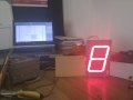
I am working on a project to drive an industrial type seven segment display. I got the code running on the prototype which i used small 12mm displays. Now the challenge is interfacing the hardware with the big 5 in displays. I am tring to drive the LEDs using the ULN2003. When I make measurements on the multimeter The seems to be nothing much happening @ the output. I have an input of 4.85 V and an output of 0.6V from the ULN2003.:confused:

Can you please assist
 

Attachments

pwdixon

Joined Oct 11, 2012
488
Need a circuit diagram of what you are doing.
Probably a part number for the parts that worked and a part number for the parts that don't work would help too.
 

MrChips

Joined Oct 2, 2009
30,701
ULN2003 is an inverting driver. Also it has open collector output.
Need circuit diagram in order to provide help.

BTW where did you get the 5" displays?
 

ErnieM

Joined Apr 24, 2011
8,377
Ditto, where did you get the display? Love em. Have no need but might get some anyway. ;-)

Also, having the spec for it lets us see how to drive it. Knowing "UNL2003" is only half the story.
 

elec_mech

Joined Nov 12, 2008
1,500
Welcome to AAC.

As THE_RB said, I'd guess you're using too low a voltage. 5" displays will require more than 5V to operate.

BTW where did you get the 5" displays?
Looks like Futurlec.

If this is the case, those require 9.25V according to the website (though be leery, they've posted incorrect data before).

A ULN2003 is only going to work with a common anode (CA) display. Is yours common anode or common cathode?

Assuming CA, if I'm doing my math right (it's late), you could feed the CA pin(s) 12VDC, then connect each cathode segment in series with a 100-150Ω resistor to each ULN2003 pin. Make sure pin 8 of the ULN2003 is connected to ground. I'm assuming your micro takes 5VDC. This will work as long as you tie the GND from both the 5VDC and 12VDC supply together.

I have an input of 4.85 V and an output of 0.6V from the ULN2003.
How are you taking this measurement?

As others have said, a schematic showing how you've got everything connected will help us help you immensely. If nothing else, sketch something on a napkin, take a picture, and post it here.
 

djsfantasi

Joined Apr 11, 2010
9,156
Surely if the OP didn't have enough volts then the picture he posted wouldn't have had the LEDs lit?
Interesting point. Let's assume it's not a power issue for a moment.

The OP stated that with an input (to the ULN2003?) of 4.85v his output was 0.6v. To be expected as noted in elec_mech's post. And assuming the display is common anode, all segments would be lit as in the picture. I'd be interested in the case where the circuit outputted a mix of 4.85v and 0v.

I'd REALLY be interested in a schematic!
 
Top