I am doing experiments on photobiomodulation using pulsed Infrared LEDs. So one LED with one wavelength when it gives pulsing output, another wavelength LED can be used simultaneously with inverted power supply.
still does not explain why this has to be inverted phase but i guess you would want to change the duty cycle at some point and perhaps you want that to have a blend of different wavelengths controlled by PWM.
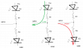
since chosen LEDs draw very little current, and GPIOs can both sink and source current, both LEDs can be driven by same GPIO. when GPIO is low , one LED is lit (D1), when it is high, the other LED is lit (D2). this way all you need is one extra resistor.
still does not explain why this has to be inverted phase but i guess you would want to change the duty cycle at some point and perhaps you want that to have a blend of different wavelengths controlled by PWM.
since chosen LEDs draw very little current, both can be driven by same GPIO. when GPIO is high, one LED is lit, when it is low, the other LED is lit. this way all you need is one extra resistor.
I use this arrangement to show bit status (HI/LO) on some digital logic demonstrator circuits in which students build gates using various discrete components, first manual switches, then relays, then MOSFETs. It has another advantage in that it shows floating signals because both LEDs turn on, albeit much more dimly, which is fine for my purposes.
still does not explain why this has to be inverted phase but i guess you would want to change the duty cycle at some point and perhaps you want that to have a blend of different wavelengths controlled by PWM.
since chosen LEDs draw very little current, and GPIOs can both sink and source current, both LEDs can be driven by same GPIO. when GPIO is low , one LED is lit (D1), when it is high, the other LED is lit (D2). this way all you need is one extra resistor.
LEDs have different voltages, one LED needs 5 Volts, another 0.8 Volt and 6 V depending upon their making for various wavelengths. So I have separate voltage sources with resistors to provide appropriate voltages and I need to pulse them.
LEDs have different voltages, one LED needs 5 Volts, another 0.8 Volt and 6 V depending upon their making for various wavelengths. So I have separate voltage sources with resistors to provide appropriate voltages and I need to pulse them.
Separate voltage sources? All you need is separate resistors. It is far more important to regulate the current to the LEDs. The voltage will sort itself out if you have the appropriate current.
Separate voltage sources? All you need is separate resistors. It is far more important to regulate the current to the LEDs. The voltage will sort itself out if you have the appropriate current.
I use a SMPS power supply for Desktop Computer. It has 3.3 V, 5 V and 12 V output. Based on LED's Forward Voltage and Forward current I calculate appropriate resistance and use it in series with LED.
I use a SMPS power supply for Desktop Computer. It has 3.3 V, 5 V and 12 V output. Based on LED's Forward Voltage and Forward current I calculate appropriate resistance and use it in series with LED.
1 mA is not the current of the LED. It is the current drawn by a switching circuit that switches the supply voltage to the LED s. For each LED of different Vf, I use separate switching circuit.
I googled photobiomodulation to try to understand what I think you want. It seems that the to dose of betwee 5 anf 50 joules per square cm has been tried. But it does not say that for a dose of 5 jouls per square cm if that was delivered as 1 watt for 5 seconds or 10 watts for 0.5 seconds. Is this what your experiment is trying to determine ? (What is the optimum way a given dose is delivered.) So you want to be able to adjust the power level and the duration.
Les.
What kind of LED's are you using? Ones I'm familiar with come in the following forward voltages: RED, typically around 2Vf. (mine is Super Bright 5mm Red at 1.95Vf). YELLOW: 2.01Vf. GREEN 2.92Vf. BLUE (3mm) 2.82Vf. WHITE 2.97Vf.
Those are the LED's I have. Those are the actual measured numbers based on running them at 10mA from a 5V supply. LED's are current based devices. You can power them from any voltage equal to or greater than their Vf. 3.3V, 5V, 12V, 24V, 100V • • • etc. You control them by limiting the current to them. If you use AC then you need to protect against reverse voltage breakdown. If you wanted to use 100V for a Yellow LED (such as mine) and you wanted it to run at mid range brightness (10mA) then you subtract the Vf from the source voltage. Then you divide the result by the desired amperage (0.01A) to get the proper resistance needed. THEN you have to calculate the total wattage and choose a resistor that can handle the wattage.
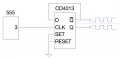
However, I still don't understand the need to have two pulses that are 180˚ out of phase. Going on that premises; I'd use a flip flop to separate the two phases. With each clock pulse the FF changes from Q HIGH and NOT-Q LOW to Q LOW and NOT-Q HIGH. Now you have two signals that are at 50% and always 180˚ out of phase.
I'm not certain that is what you're after, but from what I've read so far it seems like you're dead set on having two square waves 180˚ out of phase.
For clarity:
The 555 produces the clock pulse rate you desire. It doesn't need to be 50%. You can even use whatever clock source you choose. The 4013 (half shown) has two outputs "Q" and "NOT-Q". (NOT-Q has the bar over the Q) One is exact opposite of the other. That will give you two square waves simultaneously and at the same frequency. One is high when the other is low. Always.
I don't know off hand how much current the 4013 can sink or source. For that you'll have to look up the data sheet. I show a CMOS chip in my diagram. There are other versions with different current characteristics. This is my approach to give you the two opposing square waves.
1 mA is not the current of the LED. It is the current drawn by a switching circuit that switches the supply voltage to the LED s. For each LED of different Vf, I use separate switching circuit.
For the simplest inversion scheme to drive LEDs, use a CMOS HEX INVERTER/BUFFER (CD4049) IC!if you set the voltage to the proper level, the current will be OK for many LED types. And no series resistor required in the drive circuit.
I’d argue, that’s the problem you need to solve, it’s a coding problem, forget the additional hardware. I guess it depends on the complexity of the code in your application and how important the delay between one output changing and the other output changing, but if you sniff the output with a second pin and invert in code to drive another output pin, unless it’s needed to run blisteringly fast that should do it.

 Facebook
 Google
 GitHub
 Linkedin