Interchange HIGH and LOW of PWM

Thread Starter

sab201

Joined Nov 18, 2023
322
Good Day,

I have pwm output of 3.3 Volts HIGH and 0 Volts LOW with 50% duty cycle coming out from Raspberry Pi 5.

I want a circuit that converts the highs to lows and lows to high so I have two outputs simultaneously that I can use in parallel.

Please suggest me a circuit to do this.
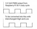
sketch-1789635015786~2.jpg

Thanks
 

Thread Starter

sab201

Joined Nov 18, 2023
322
What is the load/current required of the circuit?
A 2n7000 Mosfet on each of the output rails will invert if the current is low.
.
Ok the load current is 1 to 2 mA.

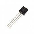
Please let me know how to connect the 2n7000 Mosfet on each of the output rails.

2n2700_lrg.jpg

The Gate Drain Source connections.

Thanks.
 
Last edited by a moderator:

ericgibbs

Joined Jan 29, 2010
21,573
Hi sab,
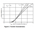
This is the PDF for the 2N700, check the pin layout.
E

Added: as you are using pwm output of 3.3 Volts HIGH and 0 Volts LOW.

The 2n7000 may not fully switch On at 3.3V

A 13 Sep. 17 15.50.png
 

Attachments

Last edited:

MaxHeadRoom

Joined Jul 18, 2013
30,810
The FET provides inversion between input and output, the gate can be directly connected to the Pi5 output but better still through a 1k resistor.
 

ericgibbs

Joined Jan 29, 2010
21,573
hi sab,
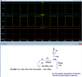
Check this transistor circuit.
E

Added: as you are using pwm output of 3.3 Volts HIGH and 0 Volts LOW.

The 2n7000 may not fully switch On at 3.3V

EG 2222.jpg
 

B-JoJo-S

Joined Jan 3, 2026
541
So far I've refrained from giving an answer. I best like post #8. But I have refrained till now only to ask one obvious question: If you want to convert highs to lows and lows to highs - you shift the signal by 180˚. What do you hope to gain by doing this? In other words: "Why do you want to shift the signal? It's still 50% high and 50% low." Unless you want to convert the highs to negative highs; for what purpose I can't think of.
 

Thread Starter

sab201

Joined Nov 18, 2023
322
hi sab,
Is this what you are asking? 3.3V PWM to Inverted 5V PWM.?
If not, post a sketch.
E
No I edited that. I thought 2N7000 MOSFET cant switch on at 3.3 Volts. So if I can use a 5 Volts instead. But if a 2N222 can switch ON at 3.3, then that 5 Volts will not be needed.

No I wasn't asking about inverting a 3.3 V PWM to inverted 5 V PWM. Once I can invert this 3.3 Volt PWM I can use switching MOSFETS to switch 3.3 Volts, 5 Volts or 12 Volts. I have circuits for that.

I only need to invert a 3.3 Volts PWM. If a 2N222 in post #8 circuit can do it, I will go with it.
 

crutschow

Joined Mar 14, 2008
38,819
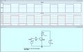
You could also use two of the inverters in a 74HC04 hex inverter IC (LTspice sim below):
Just one inexpensive part required for the two signals.

Rload is the simulation load and is not needed in the real circuit.

1789662931961.png
 

Thread Starter

sab201

Joined Nov 18, 2023
322
You could also use two of the inverters in a 74HC04 hex inverter IC (LTspice sim below):
Just one inexpensive part required for the two signals.
Rload is the simulation load and is not needed in the real circuit.
Thanks.

What is the maximum frequency that the 74HC04's inverter can handle...

I need to switch PWM of upto 2 kHz
 

Thread Starter

sab201

Joined Nov 18, 2023
322
So far I've refrained from giving an answer. I best like post #8. But I have refrained till now only to ask one obvious question: If you want to convert highs to lows and lows to highs - you shift the signal by 180˚. What do you hope to gain by doing this? In other words: "Why do you want to shift the signal? It's still 50% high and 50% low." Unless you want to convert the highs to negative highs; for what purpose I can't think of.
I am doing experiments on photobiomodulation using pulsed Infrared LEDs. So one LED with one wavelength when it gives pulsing output, another wavelength LED can be used simultaneously with inverted power supply.
 
Top