Integrating zener diode into my circuit

Thread Starter

Fobio Design

Joined May 11, 2016
17
Hello-

Hope you are all having a wonderful day so far.

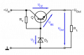
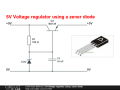
I am looking to use a zener diode in my circuit (5.1V & 5W). My supply voltage is a 9V 600mAH battery.

My question is what type of resistor and NPN transistor I would need to use in my circuit before the zener diode?

Thank you!
 

ScottWang

Joined Aug 23, 2012
7,501
Is this a homework or personal study?
Your circuit (5.1V & 5W), so I = W/E = 5W/5.1V = 0.98A
If the above is true then the current of your 9V 600mAH battery will be not enough for the circuit.

Are you trying to make a 5V/5W power supply from 9V battery (or any 9V power supply) using the npn R+zener diode+n bjt?

What is your circuit (R+zener diode+bjt, no matter will it work or not)?
 

Thread Starter

Fobio Design

Joined May 11, 2016
17
Is this a homework or personal study?
Your circuit (5.1V & 5W), so I = W/E = 5W/5.1V = 0.98A
If the above is true then the current of your 9V 600mAH battery will be not enough for the circuit.

Are you trying to make a 5V/5W power supply from 9V battery (or any 9V power supply) using the npn R+zener diode+n bjt?

What is your circuit (R+zener diode+bjt, no matter will it work or not)?
Thanks for your reply. It is for a personal project. I am trying to implement a voltage regulator into my circuit. I have attached a picture of what I want the circuit to look like. I am just confused on what resistor and transistor I would need to use with the battery supply voltage I have to create 5V and 6W.
 

Attachments

Veracohr

Joined Jan 3, 2011
783
I assumed 5W is just the rating of the zener the OP has, not the target capacity of the supply.

You'd probably be better off using an IC regulator like 7805.
 

ScottWang

Joined Aug 23, 2012
7,501
Thanks for your reply. It is for a personal project. I am trying to implement a voltage regulator into my circuit. I have attached a picture of what I want the circuit to look like. I am just confused on what resistor and transistor I would need to use with the battery supply voltage I have to create 5V and 6W.
I thought the circuit would be like that, because that is the basic circuit.
What is your application of the Load?

The Vout = Vz + Vbe
Ic = Ib*10
Iout = 6W/5V = 1.2A
Ie = Iout
= Ic+Ib
= Ib*10+Ib
= Ib*11

Ib = Ie - Ic
= 1.2A/11
= 0.109 A
= 109 mA

If you using the zener diode + bjt circuit, when the load does not draw the current then the zener will be drawing too much current.

If you using two stages as 2sc1384 + mje3055 + 6.8V zener diode and then the Vout will be as
Vout = 6.8V-0.7V-0.8V = 5.3V

Mje3055_Ic and Ib in sat.gif

Another choice is using LM2576-5V_12V, 3A

Whatever which one you choose, the most important thing is the input current should be as
Ii = 1.2 A*(1+20%) = 1.44 A is better.
 

Thread Starter

Fobio Design

Joined May 11, 2016
17
Sorry for all the confusion. I have attached a new file of the setup I want. I am using a 5.1V 5W zener, I am just confused on what type of resistor and transistor I should be using.
 

Attachments

ScottWang

Joined Aug 23, 2012
7,501
Sorry for all the confusion. I have attached a new file of the setup I want. I am using a 5.1V 5W zener, I am just confused on what type of resistor and transistor I should be using.
Iout = 5W/5V = 1A
Ib = 1A/11 = 90.9 mA
Vout = Vz -0.8V = 5.6V = 4.8V
I_R1 = Ib + Izd = 90.9 mA + 10 mA = 100.9 mA
V_R1 = 9V - 5.6V = 3.4V
R1 = 3.4 V/100.9 mA = 33.7 Ω = 33 Ω

As IN4734, it has Imax = 162 mA, and we will use it less then I = 162 mA(1/3) = 54 mA, and the Ib as 90.1 mA, so it has risk that you don't know when the zener will be burned, because too hot.

Please reread my post on #6 to know more about the details and calculation.
 
Top