Insufficient I/O ports in MCU

Thread Starter

raychar

Joined Nov 8, 2011
82
Hello, everybody,

I have many I/Os lines in my circuit and the current PIC16F877A can't fullfill the requirement. Currently, except the MCLR, OSC1, OSC2, PGD, PGC, PGM pins, all others are used. I also use multplexing method and input and output lines on the same port method. As I don't want to make the circuit and program so complicated and also now, still is of shortage five I/Os. Are there other MCU models which have more I/O pins that I can used instead of this one or some other methods?

Thanks,
 

Markd77

Joined Sep 7, 2009
2,806
Read the first link in the first post of the sticky "A goldmine for the PIC programmer" at the top of the embedded forum. It has lots of tips and tricks.
 

Thread Starter

raychar

Joined Nov 8, 2011
82
There a lot of tips and tricks that are very useful. I confess I would have definitely progressed a lot if I read it some time ago. There are many
circuits and designs that I tried before and problems encountered before..

For the several keys on a port using RC charging time method, it is a bit difficult for me to write the program indeed...

Are there other simpler methods ?

Thanks,
 

Markd77

Joined Sep 7, 2009
2,806
It's hard to say without more detail.
Recently I made a project using a resistor ladder and one ADC pin to read ten buttons. Of course it only works if only one button is pressed, but sometimes that is all you need.
 

MrChips

Joined Oct 2, 2009
35,177
Every situation is different. There are no hard and fast rules on how to accommodate all your I/O needs.

The first step would be to make a list of all the I/O pins you need and their functions.
Some functions may be able to share I/O pins.

The first solution, of course, is to go with a chip with a higher pin count.
Sometimes this is not acceptable. In that case, you start looking at multiplexing and I/O expansion taking advantage of SPI, I2C, UART interfaces etc.

In a complex system integration design, it is possible to go to a RS-485 network. I have do this very successfully in industrial applications.
 

John P

Joined Oct 14, 2008
2,068
I'd say first of all see which functions you can multiplex (pushbuttons and LED indicators would be easiest) and if that doesn't help enough, the first thing to try would be SPI. That's very easy to use and interface with other hardware.
 

takao21203

Joined Apr 28, 2012
3,702
You need a second PIC for the I/O, which you can transfer via a 3-wire or 4-wire bus.

DAT - serial data
CLK - serial clock
RDY - strobe from the slave that it is ready to accept data (must cycle through 1-0-1 to avoid out of sync).
SEL - select chip line if you use more than one slave PIC, so you can share the 3-wire serial bus for more than one chip.

All this can be done in software.

If you use the hardware serial port, you can get away with less I/O even. But then you need to design interrupt handlers, and buffering.

Depends mainly how fast you need a response.

Using a 18F etc. with more pins is another option.
 

Thread Starter

raychar

Joined Nov 8, 2011
82
Hello,

Thanks for the information.

Some time ago, i have sucessfully used resistor laddler method in a port to detect several input lines. However, I can apply it only in several positions type sliding switch. It stays on a position and have fixed voltage and then another position of another fixed voltage. I can't apply it in momentary buttons in which voltage rises back to high voltage (5V) when it is released, in the course, different voltages are sensed and make wrong judgement.

Can anyone suggest how to improve it?

Thanks,
 

Markd77

Joined Sep 7, 2009
2,806
I did it a similar way to button debouncing:
Every 20ms read ADC
Convert ADC to button number
Compare to button number from 20ms ago
If it's the same the button is pressed, if not ignore it and save the button number for next time.
Here's the schematic:
http://www.marksphotos.info/3w1.gif
Here' some scrappy, badly commented code (works fine though):

Rich (BB code):
    bsf ADCON0, 1            ;start conversion 
adc_wait2 
    btfsc ADCON0, 1
    goto adc_wait2
     
    call get_button
    movwf count2
 
    subwf AN2_old_val, W        ;is it the same as last time? 
    btfss STATUS, Z
    goto not_new_number_press
;should do something if button changed     
    movf count2, W                ;is it button release? 
    btfsc STATUS, Z
    goto number_release
 
    btfsc flags, number_button_pressed
    goto not_new_number_press
    goto new_number_press
 
number_release 
bsf flags, number_button_released 
goto not_new_number_press 
 
new_number_press 
bcf flags, number_button_released 
    bsf flags, number_button_pressed
    movf count2, W
    movwf number_button_val
 
not_new_number_press 
movf count2, W 
movwf AN2_old_val
Rich (BB code):
get_button 
movlw d'243' 
subwf ADRESH, W 
btfsc STATUS, C 
retlw d'10' 
 
movlw d'217' 
subwf ADRESH, W 
btfsc STATUS, C 
retlw d'9' 
 
movlw d'191' 
subwf ADRESH, W 
btfsc STATUS, C 
retlw d'8' 
 
movlw d'165' 
subwf ADRESH, W 
btfsc STATUS, C 
retlw d'7' 
 
movlw d'139' 
subwf ADRESH, W 
btfsc STATUS, C 
retlw d'6' 
 
movlw d'113' 
subwf ADRESH, W 
btfsc STATUS, C 
retlw d'5' 
 
movlw d'87' 
subwf ADRESH, W 
btfsc STATUS, C 
retlw d'4' 
 
movlw d'61' 
subwf ADRESH, W 
btfsc STATUS, C 
retlw d'3' 
 
movlw d'35' 
subwf ADRESH, W 
btfsc STATUS, C 
retlw d'2' 
 
movlw d'9' 
subwf ADRESH, W 
btfsc STATUS, C 
retlw d'1' 
 
retlw 0
 
Last edited:

MMcLaren

Joined Feb 14, 2010
861
Hello, everybody,

I have many I/Os lines in my circuit and the current PIC16F877A can't fullfill the requirement. Currently, except the MCLR, OSC1, OSC2, PGD, PGC, PGM pins, all others are used. I also use multplexing method and input and output lines on the same port method. As I don't want to make the circuit and program so complicated and also now, still is of shortage five I/Os. Are there other MCU models which have more I/O pins that I can used instead of this one or some other methods?

Thanks,
Can you show us what your circuit looks like now? That is, what do you have connected to the microcontroller?

Regards, Mike
 

Thread Starter

raychar

Joined Nov 8, 2011
82
Hello,

My circuit mainly consists a number of button switchs and LED indicators to do the logic functions to control two small DC voltage motors, in which one draws fairly large current that will be driven by relays or mosfets, 20A. Sorry that i can't post it because it was just sketched on paper. Actually, it is applied in industrial device. I may switch to 18F controller for the full-bridge PWM that it has, however, as the response is not so critical in my design, so I am still pending to do it.

BTW, I find PIC16F1526 from the Pagehandler of PIC website:

>it is SMD type, i need to upgrade my knowlegde and skill?? Yes, it is 2013, as an amateur like me, oh!?..
>will my debugger ICD2 be suitable for it? Any suggestion?
>I haven't any demonstration board for 18F and 16F in the past and usually assembling the trial boards on my own to do debugging.
>what type of demo board shall i need to purchase for this IC?
>I use MPLAB IDE v8.10 and PICCLITE and old version PIC18 complier, what types and version of softwares shall i need for it?
>will this 16F1526 be a suitable choice or any suggestions?

Sorry that i have limit knowlegde outside 16F877A, 677, 628 and 18F482 microcontrollers.

Thanks,
 

MMcLaren

Joined Feb 14, 2010
861
My circuit mainly consists a number of button switchs and LED indicators to do the logic functions to control two small DC voltage motors...
Unfortunately, that doesn't help much. How many switches? How many LEDs? How many I/O pins for motors? Please put some effort into your answers to match the effort we're willing to invest to help...
 

ErnieM

Joined Apr 24, 2011
8,415
>it is SMD type, i need to upgrade my knowlegde and skill?? Yes, it is 2013, as an amateur like me, oh!?..
With a small iron tip and a magnifier, thin solder and some solder wick anyone can solder tiny SMD parts.

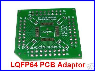
Adapter boards are essential to wire these. An adapter gets the close leads onto a 0.1" center which normal humans can handle. QUAD flatpacks have leads on all 4 sides and hence don't work in solderless breadboards. That's not an issue for anyone with a soldering iron and some wire.

>will my debugger ICD2 be suitable for it? Any suggestion?
Pick a PIC device, open MPLAB, and when you hit the menu for Configure | Select device you will see all the supported programmers & debuggers for that PIC. So pick a PIC your ICD works with.

>I haven't any demonstration board for 18F and 16F in the past and usually assembling the trial boards on my own to do debugging.
>what type of demo board shall i need to purchase for this IC?
I am not aware of any demo boards, I'm sure they exist but I toss mine together myself.

>I use MPLAB IDE v8.10 and PICCLITE and old version PIC18 complier, what types and version of softwares shall i need for it?
I use MPLAB (non-X) and like it, I keep hearing about quirks in MPLAB-X.
The C18 compiler is still a free download. You get 60 days free for the full version, after that it works but you get bigger code.


>will this 16F1526 be a suitable choice or any suggestions?
Selector guide says 55 I/O pins, best check that in the data sheet! If you're comfortable with PIC16 then stay with it, though I don't see much of a difference between PIC16 and 18 when working in C., except the PICs with more memory are PIC18's.

BTW I keep a stock of adapters such as this on hand:


Good thing I keep some around, as my favorite Chinese vendor (free shipping but takes 2 weeks) is closed till 2/15 for the Chinese New years. Some vendors from Thailand have PIC specific adapter boards with placed for decoupling caps and even the pins for a PICkit.
 

takao21203

Joined Apr 28, 2012
3,702
>it is SMD type, i need to upgrade my knowlegde and skill?? Yes, it is 2013, as an amateur like me, oh!?..
With a small iron tip and a magnifier, thin solder and some solder wick anyone can solder tiny SMD parts.
I use all regular soldering wire, a broad tip, sometimes also a desoldering pump and a magnifying glass.

Putting a TQFP64 adapter board on flywires is a tedious work, but, it is even self supporting with so many wires :)
 

Thread Starter

raychar

Joined Nov 8, 2011
82
Many thanks for the suggestions, especially, the schematic and codes. It is amazed that the sucess of number of buttons on the same pin, i usually do only 4~5 buttons.

Regards,
 

takao21203

Joined Apr 28, 2012
3,702
If you want a 32 keys pad, make a matrix like for LEDs, use a shifter for the columns if you like, and test each with a "1" on the columns and see if there is a "1" on the rows.

Flywires yes, it is a lot of work for 64 lines. Not even to think about 80 or 100 wires. Actually I also have the SMD chips here and tried with the layout. Interleaving the RAM chips requires a lot of PCB space, and latches are required as well.

Looks futuristic at least, kind of Yesterday's tomorrow.
 

Attachments

Top