Instrumental amplifier INA128 muscle sensor designing

Thread Starter

Hamas Ahmad

Joined Apr 12, 2022
13
Hi,
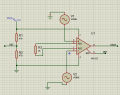
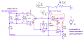
I am working on INA128 instrumental amplifiers for taking the signal from forearm muscle. I am operating on 5v single power supply to power up the INA128. I am dividing these 5v into two voltages with respect to 2.5 reference voltage(5v to 2.5v and 2.5v to 0v). The maximum rail is 5v and minimum rail is 0v. The output signal is swing with respect to reference voltage that is 2.5v. I am reading the signal from Arduino serial monitor. But, I am facing the problem reference voltage not stable. it is changing by the change of gain resistor. it should be on 2.5v if the reference is 2.5v. I have three electrodes 2 for inputs signal and 3rd one is reference electrode that is 2.5v. The integer values reading from 0 to 1024. The signal should swing on 512 integer if Vref is 2.5v. Please help me in this problem.

Thank You
Hamas Ahmad
 

Attachments

ericgibbs

Joined Jan 29, 2010
18,766
hi Hamas,
This is a similar circuit to yours, it shows how the Ref Pad voltage of 2.5V created and applied.

How are you creating the Vref in your circuit.

I will run your circuit in a LTspice simulation and post what I see.

E
EG 1569.gif
 

Thread Starter

Hamas Ahmad

Joined Apr 12, 2022
13
hi Hamas,
This is a similar circuit to yours, it shows how the Ref Pad voltage of 2.5V created and applied.

How are you creating the Vref in your circuit.

I will run your circuit in a LTspice simulation and post what I see.

E

S
hi Hamas,
This is a similar circuit to yours, it shows how the Ref Pad voltage of 2.5V created and applied.

How are you creating the Vref in your circuit.

I will run your circuit in a LTspice simulation and post what I see.

E
Sir, can you explain little about reference pad in this circuit and why 10k ohm resistors are used in between pad1 and pad2.
 

ericgibbs

Joined Jan 29, 2010
18,766
hi Hamas,
The 10k resistors are to represent the skin/muscle resistance of the human body.

There must be a conduction path for the electrical muscle signals, also there must be a conduction path to the Vref pad.

Have you done any research on this EMG measurement technology.??

E
Clip:

I want to measure EMG activity of muscles. the requirement is skin resistance should be less then 5k ohm. how to measure this resistance?
As per SENIAM standards, skin must be shaved and abraded with alcohol to reduce skin resistance upto 5k ohm, prior to experiment. one must keep on abrading skin until resistance is less then 5k ohm.
question is how to measure this skin resistance? with simple DMM? if yes then what should be the distance between the terminals of DMM?


C
 
Last edited:

Thread Starter

Hamas Ahmad

Joined Apr 12, 2022
13
hi Hamas,
The 10k resistors are to represent the skin/muscle resistance of the human body.

There must be a conduction path for the electrical muscle signals, also there must be a conduction path to the Vref pad.

Have you done any research on this EMG measurement technology.??

E
Clip:

I want to measure EMG activity of muscles. the requirement is skin resistance should be less then 5k ohm. how to measure this resistance?
As per SENIAM standards, skin must be shaved and abraded with alcohol to reduce skin resistance upto 5k ohm, prior to experiment. one must keep on abrading skin until resistance is less then 5k ohm.
question is how to measure this skin resistance? with simple DMM? if yes then what should be the distance between the terminals of DMM?


I am beginner in EMG technology and not much knowledge. I am doing research on it. Thanks for your help.
 

Thread Starter

Hamas Ahmad

Joined Apr 12, 2022
13
hi Hamas,
This is a similar circuit to yours, it shows how the Ref Pad voltage of 2.5V created and applied.

How are you creating the Vref in your circuit.

I will run your circuit in a LTspice simulation and post what I see.

E
View attachment 265202
Hello Sir, I hope you are doing well. The low pass of 72 hertz in this circuit the output is working fine but i changed this low pass filter with 7 hertz high pass and with any other high pass, the output of the signal is zero. what is happening here can u guide me sir in this stuff.
 

Ian0

Joined Aug 7, 2020
9,667
Are you actually interested in the standing DC voltage across your probes? If not, then roll off the DC gain with a capacitor in series with Rg.
 

Thread Starter

Hamas Ahmad

Joined Apr 12, 2022
13
Hi Hamas.
Your LTS circuit works for me, which part of the circuit is causing your problem.?

E
View attachment 267470
Yeah Sir, here it is working fine but in the hardware the signal form muscle is very low. Its about 0.01V. Now my next step is creating a band pass filter to remove low and high frequencies with 10 times gain. The band pass is 7-500Hz. When i applied 7hz high pass on the signal. The signal became zero.
 
Top