Facebook
 Google
 GitHub
 Linkedin
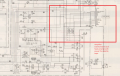
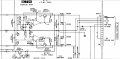
Sony vintage stereo casette tape TC-D507
It will be very difficult to find that exact input voltage per connector pins from this casette tape.
I have not the amplifier (TA-D507) wich feed external with power this casette tape. The input power connector (system control 2) are 15 pins, from wich are used seven pins.
Thanks !
It will be very difficult to find that exact input voltage per connector pins from this casette tape.
I have not the amplifier (TA-D507) wich feed external with power this casette tape. The input power connector (system control 2) are 15 pins, from wich are used seven pins.
Thanks !
Attachments
-
 126 KB Views: 30