Facebook
 Google
 GitHub
 Linkedin
Hello,
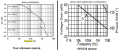
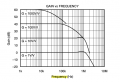
I am using an amplifier with a gain of 100 (40dB) to amplify 20-400 Hz signals.
The pic from the data sheet shows that the minimum frequency for 40dB needs to be 1kHz.
What happens if the frequency is lower than 1kHz? will it affect the amplification?
thank you
I am using an amplifier with a gain of 100 (40dB) to amplify 20-400 Hz signals.
The pic from the data sheet shows that the minimum frequency for 40dB needs to be 1kHz.
What happens if the frequency is lower than 1kHz? will it affect the amplification?
thank you
Attachments
-
 39.1 KB Views: 19