Variable output of AD620 with input frequency

Thread Starter

Devendra042

Joined Sep 16, 2024
6
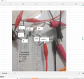
I measure multi times output of AD620.but its output change with
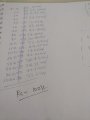
1. when input frequency change like f=50,60,70....
2. Same frequency measure different output like
first time f=50 ,output=120mv
second time f=50,output =150mv
but I observe that output don't depend on input frequency its means outvalue only depend on Rg value
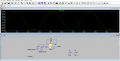
I try different method solve this problem like Decoupling ,AC coupling and other manufacturing company AD620 use but problem is same .I try this process approx 6month but I don't find satisfied result. I use LTspice for simulation ,i found desirable result but same method apply on breadboard i face variable output problem.
I waiting your reply
 

Attachments

Last edited:

ericgibbs

Joined Jan 29, 2010
21,390
Hi D,
The initial test of your circuit using my AD620 model, shows this BW response.

Run the same test on your model and post the BW plot

E
EG57_ 2078.png
 

Thread Starter

Devendra042

Joined Sep 16, 2024
6
Hi eric,
All is right in simulation
,but we apply at Breadboard then we face problem output variable with input frequency, I mention above breadboard reading .
 

ericgibbs

Joined Jan 29, 2010
21,390
Hi D,
One point, there is no power rail decoupling on your BBoard power rails.
Are you confident that the two Sine wave sources are giving 10mV and 20mV over the 50Hz through 1kHz range.?
Also, are you using the X10 option on your Scope probe, in order to minimise the loading caused by the probe.?

I have used the AD620 in a number of project and always found the BW to be flat, as shown in my posted for comparison simulation plot.

Another small point is the inter electrode capacitance of the BBoards.

Looking through your frequency versus mVout, which jumping high and low suggests a bad wire link connection.

For a test, try adding a 10k resistor from the signal inputs to 0V on the board

E
 

ericgibbs

Joined Jan 29, 2010
21,390
Hi D,
If the two 50hZ > 1000hZ are in phase sync, as they would be in a LTS sim, no problem
If in the hardware version, if the two frequency sources are slightly out of sync, you will have a problem.

E
EG57_ 2080.pngEG57_ 2081.png
 

Thread Starter

Devendra042

Joined Sep 16, 2024
6
Hi eric,
thank you for supporting and understand my problem ,
Actually I want to design and simulation of ECG signal by using AD620,Filter and ADC. I face problem in initial part AD620,its output is not constant using BBoard. Filter is bandwidth 1hz to 100hz only. if AD620 problem solve then we can proceed further I am struck at AD620.
 

Thread Starter

Devendra042

Joined Sep 16, 2024
6
hi eric,
nice explain with new idea , thanks bro..
I have face problem in hardware side (breadboard)for finding constant output AD620 , Give me some suggestion how to find constant output from AD620 ,at now variable output form BBread. if possible show me BBoard connection ,get desirable output
 
Top