inductor question

Thread Starter

lokeycmos

Joined Apr 3, 2009
431
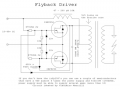
refering to the ZVS driver at this site: http://wiki.4hv.org/index.php/Flyback_transformer

could someone please explain how increasing the inductor increases output voltage and decreasing it increases current?

i really dont have a super clear understanding about how the inductance effects the circuit in this scenario. could someone please explain it to me?

disregard the high voltage part, im just wondering about the inductor part of the circuit. TY
 

SgtWookie

Joined Jul 17, 2007
22,230
Have you been on Ronald Dekker's site? He has a very good write-up on inductors, transformers, boost converters and flyback converters:
http://dos4ever.com/flyback/flyback.html

Keep in mind that if you want to build these circuits, in figure 3 and figure 16, reduce R4 to 47k to keep the output voltage at a relatively safe level.

As far as increasing the inductor increases the output voltage, etc - it's actually the ratio of turns on the primary side to the turns on the secondary side. If the secondary side's number of turns are increased, the output voltage increases and the current goes down to compensate. If the number of turns on the secondary are decreased, the voltage goes down and the current goes up.
 

Thread Starter

lokeycmos

Joined Apr 3, 2009
431
Not sure if we are talking about the same thing. i meant the inductor comming from the power source.

this is a quote from a website:

"The "47-200 µH" inductor is customized to the desired output of the FBT. In general, if one requires more voltage output, he should use a larger inductor. For more current, use a smaller value inductor"
 

Attachments

thatoneguy

Joined Feb 19, 2009
6,359
A higher inductance, when presented in a pulse/switching configuration, will not allow current to pass as easily compared to a lower inductance.

Inductors want to keep the current through them the same, no matter the level, from 0A to 250mA, to 10A, the inductor will generate an EMF to "attempt" to keep a constant current source, by increasing the terminal voltage. This is the foundation of switch mode power supplies.
 

SgtWookie

Joined Jul 17, 2007
22,230
Ahh, I see.
I haven't analyzed the circuit, but I believe the larger the 47uH-200uH inductor is, the more voltage will be across the side of the primary that gets turned on next, as when the last one gets turned off, it'll keep the current flow going by charging up the 0.68uF cap.
 

Thread Starter

lokeycmos

Joined Apr 3, 2009
431
ok, im an electronics student and have a good understanding how things work in this circuit. inductors are my weak spot. i mean i know about henry values and inductive reactanc but can you dumb it down a little bit more? ty
 

thatoneguy

Joined Feb 19, 2009
6,359
If you can think of capacitors as "Voltage Storage Devices", meaning they will dump current in an attempt to keep the voltage the same, then the complimentary component is the inductor.

Caps resist voltage changes by "absorbing" or "sourcing" the current. Inductors resist current change due to the EMF they create. If the current drops, the EMF collapses, creating voltage at the terminals to "try" to keep current flowing by "absorbing" or "sourcing" voltage.

When you mix capacitors and inductors in different ways, you end up creating tuned circuits, or switch mode power supplies. The inductor provides current at the cost of speed of operation (and parasitic resistance within inductor). Capacitors of larger values will also slow down the speeds, as they need to be charged to have any effect.
 
Top