Facebook
 Google
 GitHub
 Linkedin

Hello,
So I'm looking to make a boost regulator circuit so I started looking at basic RL circuits and I understood how they got the formula
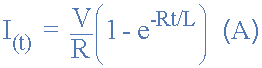
when t=0, voltage accross the inductor is E and current is 0 but then overtime the voltage accross the inductor is 0 and current accross the inductor is equal to V/R.
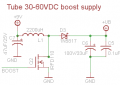
But when I look at a circuit like the one attached, how can you predict the output voltage when there is no load? When Q2 is ON, is it safe to assume that current through the inductor will eventually be equal to Vds/Rds after a certain time? But when Q2 is OFF the capacitors charge up to a certain voltage but to what value?
Thanks
So I'm looking to make a boost regulator circuit so I started looking at basic RL circuits and I understood how they got the formula
when t=0, voltage accross the inductor is E and current is 0 but then overtime the voltage accross the inductor is 0 and current accross the inductor is equal to V/R.
But when I look at a circuit like the one attached, how can you predict the output voltage when there is no load? When Q2 is ON, is it safe to assume that current through the inductor will eventually be equal to Vds/Rds after a certain time? But when Q2 is OFF the capacitors charge up to a certain voltage but to what value?
Thanks
Attachments
-
 3.8 KB Views: 52