Inductance proximity sensor output conversion to 3.3V logic

Thread Starter

zazas321

Joined Nov 29, 2015
936
Hey. Could someone give me some guidance regards to designing a circuit for proximity sensor. I am using STM32 microcontroller which is 3.3V and the proximity sensor is powered using 18V.

The link for the proximity sensor:
https://uk.rs-online.com/web/p/inductive-proximity-sensors/2811436/
https://docs-emea.rs-online.com/webdocs/1617/0900766b81617697.pdf

Is it possible that the output of the proximity sensor will be anywhere between 0 and 18V depending on how close the oebject is or the output will only have 2 states - either 18V or 0V?

Second question:
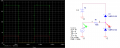
The proximity sensor above is using 3 wires, therefore I assume that 2 wires are used for power (VCC and GND) and the last one for the output. I am planning to use logic lever converter to convert sensor output to 3.3V logic:
I have found this example online, could someone advice me how to properly size the resistors for the application? I am not quite understanding why it has been chosen to use 100k Ohm resistor for the base of the transistors. I cannot identify what is the output current of the sensors or thats not relevant at all?


I have simulated the circuit using multisim live - seems to be working thought the output current is very small if that matters?
upload_2019-6-24_16-40-11.png
Any help is appreciated!
 

MaxHeadRoom

Joined Jul 18, 2013
28,698
That is a PNP output sensor so it will source into the sink base of Q1.
Just use an opto isolator 4n35 etc into the MCU.
No transistors required.
Max.
 
Adding the 4N35 will work but is no fun. If you want to calculate the values here is a quick way to get something working.

Add a resistor across the base - emitter to insure the transistors turn off when there is no input.

The first step is to look at the transistor spec sheet and find a good operating current based on the forward current gain. Select the collector resistor based on the operating point current and the supply voltage minus about 0.2 volts drop across the transistor. Divide the collector current by the minimum forward current gain to find the minimum base current. Multiply the base current by a factor of 2 or 3 to insure you are saturating the transistor. Add the current for the base-emitter resistor to the base current and calculate the value of the base resistor using the 18 volt input and this current.

This should get you close, you can tweak it in the simulator and play around with different values. You can use the same procedure for both transistors or use just one stage and invert the logic in the microcontroller.
 
Last edited:

cmartinez

Joined Jan 17, 2007
8,257
This is the circuit I use whenever I interface an inductive sensor to an MCU. The circuit assumes as 12V power supply for the inductive sensor, and a 5V interface for the MCU. It's a simple voltage divider, plus a few components to protect the MCU because normally the sensor is connected to a very long wire. There are no transistors in the circuit. And BTW, there are inductive sensors out there that are not just discrete (active/inactive) in their operation, but that deliver a voltage signal proportional to the distance to the object being sensed. But to use that sort of sensor with an MCU, an ADC interface is needed.

Image00001.jpg
 

Attachments

Last edited:

Thread Starter

zazas321

Joined Nov 29, 2015
936
Thank you for all the answers! Could someone clarify what is the output of the proximity sensor? Does it have 2 states either HIGH (18V in my case) and LOW (0V)?. Or does it output voltage from 0 to 18V depending on how close the object is to the sensor.
 

cmartinez

Joined Jan 17, 2007
8,257
Thank you for all the answers! Could someone clarify what is the output of the proximity sensor? Does it have 2 states either HIGH (18V in my case) and LOW (0V)?. Or does it output voltage from 0 to 18V depending on how close the object is to the sensor.
A PNP sensor has an output that is either "floating" (high-z) or that is delivering a positive voltage which is equal to the one used to power it. That is why it's output needs to be connected to ground through a resistor, so that the MCU either reads 0V, or 5V (in the example I previously posted).

EDIT: To make things clear: the sensor you've chosen will work in a discrete way. That is, it will either be active, or inactive. And it will not output any other voltage but high-z or 18V.
 

Thread Starter

zazas321

Joined Nov 29, 2015
936
A PNP sensor has an output that is either "floating" (high-z) or that is delivering a positive voltage which is equal to the one used to power it. That is why it's output needs to be connected to ground through a resistor, so that the MCU either reads 0V, or 5V (in the example I previously posted).

EDIT: To make things clear: the sensor you've chosen will work in a discrete way. That is, it will either be active, or inactive. And it will not output any other voltage but high-z or 18V.
Thank you. I will experiment tommorow.
 

MaxHeadRoom

Joined Jul 18, 2013
28,698
IOW, it is a simple open collector bi-polar device. so it requires some kind of load to operate into.
A 'sourcing' device such as PNP, requires a 'sinking' load generally to operate.
The 3 wire open collector versions will drive low impedance loads such as a relay, for high impedance applications a 2 wire version can be used and is sourced from the device it is connected to, IOW, for a Micro input etc, it requires no separate supply.
Max.
 
EDIT: To make things clear: the sensor you've chosen will work in a discrete way. That is, it will either be active, or inactive. And it will not output any other voltage but high-z or 18V.
High Z may not be accurate, If you placed a voltmeter on the output it may never change. The leakage current when the output PNP is off will make it continue to read approximately the power supply voltage. A load is required. With 200 mA to play with a relay is a possibility, but an 18V relay isn't.

An OPTOCOUPLER would be a good bet. OPTOMOS relays and OTO-FETS would be other choices. The latter two will get you a lower LOW.

The PNP is always on, so the optocoupler with a pull up will be normally Low.
 

Thread Starter

zazas321

Joined Nov 29, 2015
936
I have implemented a simple octocoupler circuit to test.
upload_2019-6-25_9-44-30.png


upload_2019-6-25_9-44-40.png

When the switch S1 is open (sensor output 0), the microcontroller reads 3.3V, when the switch is closed, microcontroller reads 0.1V. That should work fine right.

Can you clarify what do you guys refer to as high-z? Is it not going to be 0V or GND?

The octocoupler that I have got available is:
https://datasheet.octopart.com/TLP181(GB-TPL,F,T)-Toshiba-datasheet-14046014.pdf

Would I need to worry about limiting the current output of the proximity sensor or the output is just a voltage signal ?
 
Last edited:
Can you clarify what do you guys refer to as high-z? Is it not going to be 0V or GND?
I did not see a spec about leakage current, but pretend that your switch has a 1 M resistor across it. Measuring a voltage would be confusing.
You need a load of some sort.

Would I need to worry about limiting the current output of the proximity sensor or the output is just a voltage signal ?
Current limiting is built in.
 

cmartinez

Joined Jan 17, 2007
8,257
Can you clarify what do you guys refer to as high-z? Is it not going to be 0V or GND?
High-z is a term used to refer to an extremely high impedance node in a circuit. That is, if you were to try to measure its voltage using a MM, the node behaves as if it were effectively disconnected from the circuit.
 

MaxHeadRoom

Joined Jul 18, 2013
28,698
Would I need to worry about limiting the current output of the proximity sensor or the output is just a voltage signal ?
You just need a load resistor for the O.C. collector, or simply use the opto input for the load using the simple series resistor shown, also you can do a simple inversion of the signal by using the emitter output of the opto rather than the collector, the load resistor would be used in the emitter side.
Max.
 
Top