Next, work out the base current. Then ask yourself if the previous stage can provide enough current.
If the answer is "no" then you need to add additional devices to give more gain, like @crutschow said in post #13
Next, work out the base current. Then ask yourself if the previous stage can provide enough current.
If the answer is "no" then you need to add additional devices to give more gain, like @crutschow said in post #13
Ok so lets imagine that for a 100 mA base current we get a gain of 25, meaning that the output is 250mA. What other voltage params should I take into consideration. For example. should the Vce be saturated etc...
What you want to do is quite simply impossible. Changing the bias on the transistors changes the effective resistance which will lower the current, but there is nothing you can do with that circuit to increase the current.
If we remove the redundant (error source) "Voltage Follower" we got the Gain 3x amplifier . . . which due the particular BJT power gain stage has zero crossover distortion . . .
if we replace the bjt stage with highly sophisticated dc2dc module that has a capability to ramp sufficiently fast in response to the (what it seems to be) square wave stimulus - then what the OP asks is doable . . . if he can find sponsors to this project
the alternative is simply to provide a higher supply and use the "Voltage follower" as down-scaling stage to add current
An increase in Vce will cause a slight increase in Ic due to the output conductance of the transistor (hoe).
This will look like a small increase in the gain.
Normally the change is small enough that it can be ignored, compared to the normal variation in current gain from other factors.
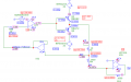
I have the below circuit and when I add the current follower op-amp circuit to my circuit it doesn't work. If I added an ideal op amp it works but when changing it to a realistic op amp it doesn't. What would be the problem?
Realistic:
Ideal:
Ohh yes I didnt notice that. The real op amp output wont reach this voltage levels.
This circuit current reachs up to 800mA. But I don't think that is it a good idea to put an op amp with an output current of 800mA or supply high voltage.
So is there any other possible solution to solve this problem?
Not quite sure what VE4 is actually meant to do.
It will try to maintain the non-inverting input at 0V, so why not simply connect the bottom of Rw to 0V ?
Not quite sure what VE4 is actually meant to do.
It will try to maintain the non-inverting input at 0V, so why not simply connect the bottom of Rw to 0V ?
The VE4 is a -22V source.
If I connect the Rw to GND, no current will flow to the current follower circuit. I am trying to find a way to convert the current flowing in the circuit to voltage for measurement reasons.
The VE4 is a -22V source.
If I connect the Rw to GND, no current will flow to the current follower circuit. I am trying to find a way to convert the current flowing in the circuit to voltage for measurement reasons.
Use a small value of shunt resistor, say 1Ω or 0.1Ω, and measure the voltage across it. That would work with a multimeter with a decent mV range. If you are measuring it with a A/D amplify the voltage with a INA180 or similar.
That's interesting. So can I say that current-sense amplifiers are better than current follower op amp for current sensing and voltage reading? Or does it depend on the case?
 Facebook
 Google
 GitHub
 Linkedin