 Facebook
 Google
 GitHub
 Linkedin
Hi All,
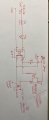
I need to power up 10 watts solenoid Valve using Arduino signal(5V) and also using EL817 & IRF5305S mosfet(pls refer my diagram). Based on the attached diagram , i am getting 12v .640ma current but need approx 840 ma current to execute my solenoid valve. Expert pls review my schematic and help me to increase the current.
Thanks
Rajesh
Attachments
-
 57.3 KB Views: 18
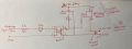

") . Note that , I don't want to use any relay for this project and the mosfet(D) need re return the required volt (12V 840ma). Pls advise.
. Note that , I don't want to use any relay for this project and the mosfet(D) need re return the required volt (12V 840ma). Pls advise.


