 Facebook
 Google
 GitHub
 Linkedin
Hi, I'm new here to the forum/website, but know a little about very simple DC circuits, switches, relays, etc. This is a fun little project I am working on and just experimenting with.
What I have:
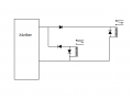
$10 RC car that runs on 3 AA batteries. There are 2 motors - one in front to make it turn L/R, one in back to make it go F/R. There is no graduation in these directions, they are full on or full off at the remote. I want to make the car go faster by increasing voltage to the rear motor. The batteries feed a "motherboard" which outputs 4.5-5V to the rear motor. When the vehicle is put in R, the "motherboard" reverses polarity. The throttle on the remote is like a center off switch: up is F, middle is brake/off, down is R.
What I've done:
I have a wall wart that can vary output voltage from 1.5-12v. I applied varying levels of VDC at the battery terminals and found that nothing happens when I apply more than 4.5V (I went up to 7.5V before stopping). Less than 4.5V and the car works fine. So there is something in the "motherboard" that protects the system from too much voltage. This tells me I can't get more power to the drive motor through the motherboard.
I've briefly applied up to 7.5V to the motor directly and it cranks wonderfully (for how long is unknown). So my next thought is how to get more power to the motor after the "motherboard. I've thought of several options, but the best I can think of is using a separate battery/power source to the rear drive motor that applies as much V as I want. I believe this will require relays, so I picked up a 5V reed relay and a 5V SPDT relay at my local radio shack.
The problem:
As I've searched/researched online and after much thinking, I've come to the conclusion that using a relay or relays in my circuit with a separate power source will work, but I will lose the ability to make the car go in R (or F, depending - only one direction will be possible).
I found this thread
(http://forum.allaboutcircuits.com/threads/reversing-polarity-with-spdt-relays.30679/)
which was helpful for me in understanding how to use 2 SPDT relays to reverse polarity, but I still can't figure out how to achieve F/R direction without one direction being "always on" in a setup like this.
Thanks!
What I have:
$10 RC car that runs on 3 AA batteries. There are 2 motors - one in front to make it turn L/R, one in back to make it go F/R. There is no graduation in these directions, they are full on or full off at the remote. I want to make the car go faster by increasing voltage to the rear motor. The batteries feed a "motherboard" which outputs 4.5-5V to the rear motor. When the vehicle is put in R, the "motherboard" reverses polarity. The throttle on the remote is like a center off switch: up is F, middle is brake/off, down is R.
What I've done:
I have a wall wart that can vary output voltage from 1.5-12v. I applied varying levels of VDC at the battery terminals and found that nothing happens when I apply more than 4.5V (I went up to 7.5V before stopping). Less than 4.5V and the car works fine. So there is something in the "motherboard" that protects the system from too much voltage. This tells me I can't get more power to the drive motor through the motherboard.
I've briefly applied up to 7.5V to the motor directly and it cranks wonderfully (for how long is unknown). So my next thought is how to get more power to the motor after the "motherboard. I've thought of several options, but the best I can think of is using a separate battery/power source to the rear drive motor that applies as much V as I want. I believe this will require relays, so I picked up a 5V reed relay and a 5V SPDT relay at my local radio shack.
The problem:
As I've searched/researched online and after much thinking, I've come to the conclusion that using a relay or relays in my circuit with a separate power source will work, but I will lose the ability to make the car go in R (or F, depending - only one direction will be possible).
I found this thread
(http://forum.allaboutcircuits.com/threads/reversing-polarity-with-spdt-relays.30679/)
which was helpful for me in understanding how to use 2 SPDT relays to reverse polarity, but I still can't figure out how to achieve F/R direction without one direction being "always on" in a setup like this.
Thanks!
 . At start-up and when stalled the motor windings will be dissipating nearly 3 times their normal (i.e. when run from 4.5V) power and could overheat.


