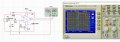
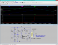
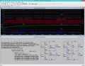
Hello. I tried a basic circuit with AD8561 comparator. The circuits and the output is under this post. I wonder that if this 800us rising and falling time can be reduce or not. Thanks in advance!
Your simulation appears to be way off.
Even with such a slow input slew rate, the output rise/fall times should be well below 100μs.
Try reducing the Maximum Timestep to 100ns.
Also try a higher input frequency (such as 100kHz) and see if that makes a difference.
what are you exactly measuring on your schematic
? the scope ports (ups! - sorry now i see it G CH1 CH2)
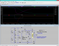
LT Spice ↓↓↓ "thinks"
(((? the digital ground -- pin 6 - is not specified in datasheet -- must dig it out from the web . . . digging . . . seems smth I/O signal chains unbound de-couple ? with common Vcc . . . am i loosing it ??? )))) http://www.analog.com/media/en/technical-documentation/application-notes/AN-352.pdf
i gess that defines it ? referencing your input to digital ground ? further chk-s . . . http://www.analog.com/media/en/technical-documentation/data-sheets/AD790.pdf
i don't have "data hold" or "latch" working in simulation ... yet
I will use it as square wave generator from the output of amplified emg signal...Amplified emg signal peak value is 5 volt and about max. 500Hz...and the referans voltage is 1.7 volt. So if the amplified emg signal is bigger than the referans the output will be 5v..and the other condition it will be zero...I want perfect square so i wonder if i can improve the rising or falling time...
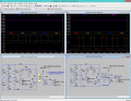
LT1016 - shows the digital ground to be the output ground - either the AD model is not fully integral - or - they define/implement it differently ??? running spice compare ...
Hello. I tried a basic circuit with AD8561 comparator. The circuits and the output is under this post. I wonder that if this 800us rising and falling time can be reduce or not. Thanks in advance!/QUOTE]Where do VCC and VEE in your simulation come from? And where did you get the model of that chip?
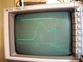
This could be a measurement problem, not the IC itself. I threw it together and the photo below shows the results. The tremendous overshoot is simply because I used a 6 inch ground lead on the scope clip, it is not really there. But you can see the risetime is well under 10 ns, as the data sheet shows it should be. Are you by chance using a x1 probe? That might load down the output but even that seems like it should give about a hundred nanosecond or so rise. Use a x10 probe and a short as you can get away with ground lead to see the true risetime.

 Facebook
 Google
 GitHub
 Linkedin