 Facebook
 Google
 GitHub
 Linkedin
Hi everyone~
I am designing a two-stage op-amp with PMOS as input transistors, with the first stage as a differential pair, while the next stage is a CS amplifier. I have designed the schematics as of below in LTSpice:

I have to design the above according to the specifications:
1) Supply voltage: 3 V (Single supply)
2) Open-loop DC gain: > 75 dB (I will be choosing 100)
3) Gain peaking: < 2 dB (ratio of maximum gain to gain at DC)
4) Unity gain bandwidth: > 20 MHz
5) Phase Margin: > 60 degree
6) CMRR : > 70 dB
7) Output voltage swing: > 1.0 V (Peak-to-Peak)
8) Offset voltage: < 2m V
9) Supply current: < 600 uA
10) Output load capacitance: 0.2 pF
11) Maximum channel width: 1000um
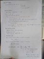
I have performed the following calculations by hand:
Page 1:

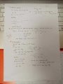
Page 2:

However, when I did a transient simulation in LTSpice, I realized that there is clipping at the top and bottom of the waveform, and I am lost at reducing the output voltage swing. The graph is shown below:

I understand that the clipping is because the voltage has swung beyond Vod6 and Vod7 (overdrive voltages for M6 and M7). May I ask how should I reduce the output voltage swing?
Thank you so much!")
I am designing a two-stage op-amp with PMOS as input transistors, with the first stage as a differential pair, while the next stage is a CS amplifier. I have designed the schematics as of below in LTSpice:
I have to design the above according to the specifications:
1) Supply voltage: 3 V (Single supply)
2) Open-loop DC gain: > 75 dB (I will be choosing 100)
3) Gain peaking: < 2 dB (ratio of maximum gain to gain at DC)
4) Unity gain bandwidth: > 20 MHz
5) Phase Margin: > 60 degree
6) CMRR : > 70 dB
7) Output voltage swing: > 1.0 V (Peak-to-Peak)
8) Offset voltage: < 2m V
9) Supply current: < 600 uA
10) Output load capacitance: 0.2 pF
11) Maximum channel width: 1000um
I have performed the following calculations by hand:
Page 1:
Page 2:
However, when I did a transient simulation in LTSpice, I realized that there is clipping at the top and bottom of the waveform, and I am lost at reducing the output voltage swing. The graph is shown below:
I understand that the clipping is because the voltage has swung beyond Vod6 and Vod7 (overdrive voltages for M6 and M7). May I ask how should I reduce the output voltage swing?
Thank you so much!
Attachments
-
 49.9 KB Views: 10
 -
 50.2 KB Views: 10
Last edited:


