Facebook
 Google
 GitHub
 Linkedin
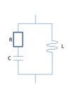
If you have a common circuit with 1 resistor, 1 capacitor, and 1 inductor. Inousoidal voltage and current is applied with angular frequency, ω.
Then you want to use the jω-method and express the total complex Impedance, Z, of the above circuit in terms of R,L,C and ω. Answer in the form Z = a + bj . Now, I know that you can usually use the "Z = Sqr(R^2 + (XL - XC)^2) formula to solve for impedance, but I'm not sure what they mean with the form "Z = a + bj"; if anyone could give me guidance in how to solve these types of problems or give a bit more insight in what they mean with "Z = a + bj" this would be really helpful. Currently studying engineering and got this question in the book, now the downside is that this book don't have solutions for all problems within it, which is why im turning towards you guys. No values for R, C, or L was given.
Then you want to use the jω-method and express the total complex Impedance, Z, of the above circuit in terms of R,L,C and ω. Answer in the form Z = a + bj . Now, I know that you can usually use the "Z = Sqr(R^2 + (XL - XC)^2) formula to solve for impedance, but I'm not sure what they mean with the form "Z = a + bj"; if anyone could give me guidance in how to solve these types of problems or give a bit more insight in what they mean with "Z = a + bj" this would be really helpful. Currently studying engineering and got this question in the book, now the downside is that this book don't have solutions for all problems within it, which is why im turning towards you guys. No values for R, C, or L was given.