Facebook
 Google
 GitHub
 Linkedin
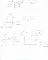
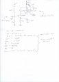
I designed and built the attached circuit, and tested it. The experimental parameters are close to the calculated parameters and so I'm satisfied I know what I'm doing to that extent. However the input and output impedances surprised me.
The input impedance, if this were low frequency, should be about 2.3kohms. But it is 560 ohms as measured with a series resistor at the input. Evidently the reactance of the capacitance seen at the input is producing this via a virtual RC filter.
The output resistance is what really surprises me. Where is this 5.6 kohm resistance coming from?
Last, I want to match the input resistance to 50 ohms via a transformer. Will a simple 1:3.3 step up transformer do this? Will the input be purely resistive?
Same with the output. I estimate a 10:1 transformer there to do the trick. But will this 50 ohms output be purely resistive?
Any help with this will be greatly appreciated. I'm still in the learning mode. Thanks!
Attachments
-
 265.8 KB Views: 66