Facebook
 Google
 GitHub
 Linkedin


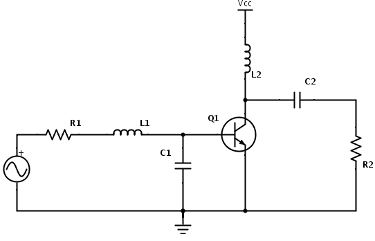
I'm reading the book RF Circuit Design by Chris Bowick currently, and I've come across something really confusing. I was running through examples with small signal amplifier design. What happened was this circuit was designed:
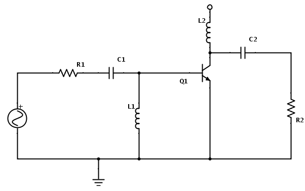
Which is a basic impedance matching network with source and load resistors. Now, that's all fine except one point- the inductor that goes up instead of down. I'm used to parallel meaning between the point and ground, but this seems like it's going to go between the point and something else, like the source voltage. Then it got worse when the bias circuitry was added:

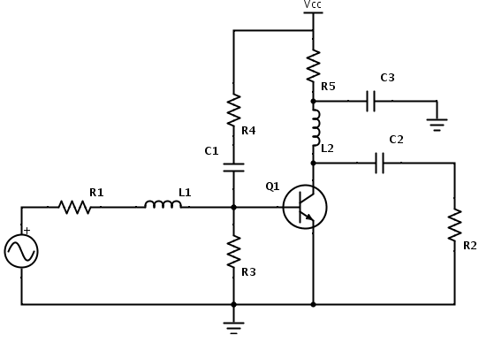
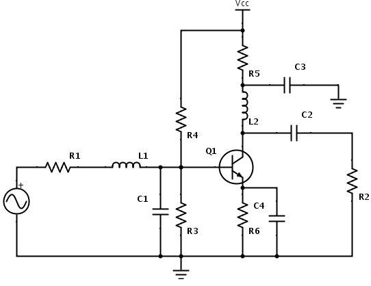
Now both the inductors are going up to the source instead of to ground. This isn't explained in the book and only this example is given with bias circuitry included.
My theory is that he's making the inductors double as chokes, thus preventing the AC signal from going to the source. The capacitors next to them sort of enforces this (all caps going directly to ground are 0.1uF bypass caps) but I don't know if I'm right. This is important for if I design other circuits with different biasing schemes, so I know what to do.
Thus the ultimate question is: why do the inductors go to the source?
And another: what would happen if the schematic called for a series inductor and parallel capacitor? Would the capacitor go to ground instead of to the source? Would it go below or above R3 in the second picture, or in parallel with R3? Help is needed and appreciated people
Which is a basic impedance matching network with source and load resistors. Now, that's all fine except one point- the inductor that goes up instead of down. I'm used to parallel meaning between the point and ground, but this seems like it's going to go between the point and something else, like the source voltage. Then it got worse when the bias circuitry was added:
Now both the inductors are going up to the source instead of to ground. This isn't explained in the book and only this example is given with bias circuitry included.
My theory is that he's making the inductors double as chokes, thus preventing the AC signal from going to the source. The capacitors next to them sort of enforces this (all caps going directly to ground are 0.1uF bypass caps) but I don't know if I'm right. This is important for if I design other circuits with different biasing schemes, so I know what to do.
Thus the ultimate question is: why do the inductors go to the source?
And another: what would happen if the schematic called for a series inductor and parallel capacitor? Would the capacitor go to ground instead of to the source? Would it go below or above R3 in the second picture, or in parallel with R3? Help is needed and appreciated people