I'm new and need some help with cd4026b

Thread Starter

rmitch

Joined May 24, 2008
24
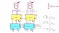
I don't understand what I'm seeing on the datasheet for cd4026b. I have 5 volt power supply and I want operate a seven segment display. My questions are, what is rated current on the outputs to the display, and what is the rated current for the inputs? I been finding mixed answers from 1ma to 25ma on the outputs. The data sheet is confusing me. I'm new and learning on my own.
I'm figuring 10ma on the inputs and 25ma on the outputs. I have nothing to backup my decision
 

Papabravo

Joined Feb 24, 2006
21,228
In short, a Series 4000 CMOS device does not have the capability to drive an LED segment except at a very dim level of brightness with a Vcc of +5VDC.
 

Thread Starter

rmitch

Joined May 24, 2008
24
hi rmitch,
Welcome to AAC.
This is a clip from the CD4026 datasheet, look at the 5V supply ratings.
E
View attachment 176869
If I understand correctly with 5v power, I will get 4.6 volts out, up to 1ma? Is this correct? Why does it show minus before the current values? And why does it show an output of 2.5 volts with a 5v supply? These are what confused me.
 

Thread Starter

rmitch

Joined May 24, 2008
24
In short, a Series 4000 CMOS device does not have the capability to drive an LED segment except at a very dim level of brightness with a Vcc of +5VDC.
Thank you. In my readings a dim display is something I was going to expect. Hope it will be fine for testing for now
. Probably will have to use transistors for the final product.
 

ericgibbs

Joined Jan 29, 2010
18,879
hi,
The minus sign indicates that the current is flowing out of the 4026 pin, ie: it is Sourcing current.
Where is it showing 2.5V with a 5V supply means that will be the output voltage when the current is at that specified current, the current pulls the output voltage down.
E

E
 

Thread Starter

rmitch

Joined May 24, 2008
24
hi,
The minus sign indicates that the current is flowing out of the 4026 pin, ie: it is Sourcing current.
Where is it showing 2.5V with a 5V supply means that will be the output voltage when the current is at that specified current, the current pulls the output voltage down.
E

E
Ok I see! That makes more sense now. So... If I'm pulling 1ma of current that will bring the voltage down to 4.6 volts. One more question... That's total output current? So I need to divide the current by how many output pins I'm using?
 

ericgibbs

Joined Jan 29, 2010
18,879
hi,
Thats the current for each output pin.
Normally that current is used to drive transistor so that a higher current can be created.
E
 

Thread Starter

rmitch

Joined May 24, 2008
24
I have a 4026 driver that outputs v+ to the segments of a cc 7 segment display. There isn't enough power do drive the display bright enough through the 4026. My thoughts were to use a transistor as a switch, power the base with the v+ output of the 4026, and switch on the proper current to each segment individually. My thoughts were to use a npn transistor for this, but circuits show an npn should go on the - side of the load, not the + side where I planned to put it. I tried this on a breadboard and it seems to work fine, but I end up with voltage going in the emitter and out the collector to the display. I just don't know if it is ok to do so this way. Circuits show a PNP should go on the + side with the base activated with 0v. It's not the way the 4026 driver works. Im new and sure I'm missing a lot.
 

djsfantasi

Joined Apr 11, 2010
9,163
I have a 4026 driver that outputs v+ to the segments of a cc 7 segment display. There isn't enough power do drive the display bright enough through the 4026. My thoughts were to use a transistor as a switch, power the base with the v+ output of the 4026, and switch on the proper current to each segment individually. My thoughts were to use a npn transistor for this, but circuits show an npn should go on the - side of the load, not the + side where I planned to put it. I tried this on a breadboard and it seems to work fine, but I end up with voltage going in the emitter and out the collector to the display. I just don't know if it is ok to do so this way. Circuits show a PNP should go on the + side with the base activated with 0v. It's not the way the 4026 driver works. Im new and sure I'm missing a lot.
  1. Use a couple of CD4069s between the outputs of the 4026 and the base of the PNP transistor. Tie unused inverter inputs to ground on the 4069. Pretty straightforward.
  2. Use NPN transistors (with appropriate resistors. A 4K pullup and a base resistor). Connect the base to the 4026 output (through the NPN base resistor), the emitter to ground and the collector to the base of the PNP (at the junction of the pullup and PNP base resistors),
 

Thread Starter

rmitch

Joined May 24, 2008
24
  1. Use a couple of CD4069s between the outputs of the 4026 and the base of the PNP transistor. Tie unused inverter inputs to ground on the 4069. Pretty straightforward.
  2. Use NPN transistors (with appropriate resistors. A 4K pullup and a base resistor). Connect the base to the 4026 output (through the NPN base resistor), the emitter to ground and the collector to the base of the PNP (at the junction of the pullup and PNP base resistors
 

Thread Starter

rmitch

Joined May 24, 2008
24
I meant to post #10 on the main forum.
Can it be moved?

MOD: Not sure what your asking.?
E
 
Last edited by a moderator:

Thread Starter

rmitch

Joined May 24, 2008
24
I meant to post #10 on the main forum.
Can it be moved?

MOD: As the Threads where covering the same Topic ie: CD4026, the two Threads have been Merged.
 
Last edited by a moderator:

Thread Starter

rmitch

Joined May 24, 2008
24
I wanted to start a new thread on the main forum with post # 10. My questons were resolved with my original post. Now I have a new series of questions that's all. I'm sorry.

MOD: I would recommend that you keep these threads merged, the people helping on the original Thread will be possibly following you.
 
Last edited by a moderator:

Thread Starter

rmitch

Joined May 24, 2008
24
  1. Use a couple of CD4069s between the outputs of the 4026 and the base of the PNP transistor. Tie unused inverter inputs to ground on the 4069. Pretty straightforward.
  2. Use NPN transistors (with appropriate resistors. A 4K pullup and a base resistor). Connect the base to the 4026 output (through the NPN base resistor), the emitter to ground and the collector to the base of the PNP (at the junction of the pullup and PNP base resistors),
Not as simple as moving my current limiting resistor to the + side of the transistor and display on - side is it....
Questions... Does the 4069 inverter do just that? Invert my + signal to - signal? Then I use the transistors to switch on/off in the correct spot of the circuit?
 

ericgibbs

Joined Jan 29, 2010
18,879
hi,
If you use an inverting IC, it will need to be inverted again, say using a low power transistor.
I see from the earlier posts you are using a 5V supply.
You could use a CD4069 or a HEF4049 inverter, with output connected to a transistor driver.
Do you know how to do that.?
E
EDIT:
This clip from the CD4026 datasheet shows a low cost option.
AA1 09-May-19 14.25.gif
 

Thread Starter

rmitch

Joined May 24, 2008
24
hi rm,
What current level do you want for each LED segment.?
E[/QUOTE
Datasheet says 25ma continuous. So that's what I'm shooting for.
hi,
If you use an inverting IC, it will need to be inverted again, say using a low power transistor.
I see from the earlier posts you are using a 5V supply.
You could use a CD4069 or a HEF4049 inverter, with output connected to a transistor driver.
Do you know how to do that.?
E
EDIT:
This clip from the CD4026 datasheet shows a low cost option.
View attachment 176934
Oh, boy. I think I'm getting over my head here with this 4026 thing. I seen the use of the 4026 in the picaxe manual, looked simple to do but not so. In short, what I'm displaying is number of button pushes. Im looking at other options that I have that may be better. I have 74192 counters, 7447 drivers that can sink 24ma, and ca displays that look like might be simpler options to use. What do you think?
 

ericgibbs

Joined Jan 29, 2010
18,879
hi,
If you have a sketch of your final circuit idea to post, it would be helpful.
How many buttons etc..

E
This is another option.
Are the 7seg LEDs common Anode or Cathode?
 

Attachments

Top