Facebook
 Google
 GitHub
 Linkedin
Having read through your posts, the easiest , and cheapest way to solve your problem is to forget about the magneto generator coil. If you supply the coils with a 12V power source and use the existing points and commutator to ground each coil in turn, this will solve your problem. You may have to replace all 6 coils or alternatively use 3 "wasted spark type coils" You must use standard ignition coils. Modern low inductance coils are not suitable . Thankfully standard 3-4 Amp primary current , ignition coils are still widely available.
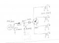
In order to prolong the life of the commutator in your magneto it might be worth considering using transistors to drive the coils , a simple type of transistor assisted ignition will suffice. There are lots of links online on how to do this.
In order to prolong the life of the commutator in your magneto it might be worth considering using transistors to drive the coils , a simple type of transistor assisted ignition will suffice. There are lots of links online on how to do this.