Hello everyone,
I'm writing this post mainly to help others who have had asked many questions in the past how to figure out the input supply leads (115V or 220V AC wires) on a salvaged UPS transformer. These transformers from a UPS are quite bulky and quite powerful and can be very useful in making high current linear DC supplies by pairing it with a high current rectifier and good filter circuit. Recently I have been trying to build a high current 12VDC bench power supply.
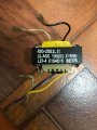
So, I have three transformers in my possession; one is from an APC 1700VA rack UPS (pic transformer 1), next is from a Tripplite Internet 700VA UPS (pic transformer 2) & another from an APC BMC 300VA UPS (pic transformer 3). The The last UPS APC BMC 300VA had a smaller transformer also (pic transformer 4), which we will talk about later in the post.
A lot of times it is easy to identify the output side of a UPS transformer as the secondary low voltage-high current side has very thick wires usually around 14AWG to 10AWG for the higher current versions. In heavier massive UPS units they usually use multiple transformers rather than using a huge single transformer from what I have seen. Now, the secondary side can be quite confusing in some transformers if there are multiple connections and when all the wires are of the same AWG or thickness it becomes even more difficult to identify the correct wiring. Most of the well known UPS brands I have come across have a fixed input supply voltage rather than dual voltages i.e., they are either a 120VAC unit or a 240VAC unit. Though there could also be units with dual supply but its not very common as the manufacturer intends to sell it to region specifically where the outlet voltage is fixed. So, if your UPS unit is meant to run only on one particular voltage (120VAC or 240VAC) then it would make the identification of the leads much easier.
Now, coming to the testing part and identification of the primary leads of the transformer. To test the transformer on of the most recommended ways is to use the resistance method. But unfortunately a lot of UPS transformers that are only meant for a single supply have additional wires on primary side but are actually part of the secondary. In many UPS units there is a 15 to 17VAC output that is present along with the primary wires. I had read from one of the threads here that the 15 to 17VAC is actually to control the relays on the board (I'm not sure if this is correct, feel free to correct me please). In some transformers like the one in transformer 2 from Tripplite the two small orange colored wires are the 15VAC outputs and the thicker white - black wires are the 115VAC inputs which is easier to identify. But on the other hand in transformer 1 from APC the blue-yellow wires produce the 16.7VAC output. It can be quite confusing sometimes. Now, in the last transformer 3 from APC it doesn't have the 16VAC line but instead it had a small separate transformer 4 to obtain that 16VAC.
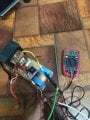
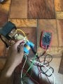
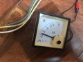
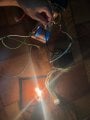
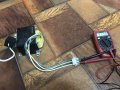
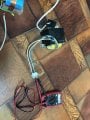
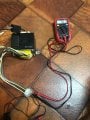
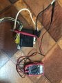
Most of the UPS output voltages are 15.3 to 15.7VAC without center tap and with center tap its 7.7VAC between the leads. So, to identify you need to obtain a 12VAC to 15VAC transformer or AC adapter. In my case I have used the Tripplite transformer 2 as my 15.3VAC source (see IMG 003) If you buy an AC adapter make sure the output is in AC voltage and not DC! If its DC just remove the rectifier + filter circuit and use the output from the transformer directly. Next feed the low voltage 12 - 15VAC supply to the thick secondary low voltage leads of the UPS transformer you are testing (in my case:see attachment IMG 004 & IMG 006). Avoid the center tap winding in the secondary (low voltage thick winding) of the UPS transformer. Now, take a multimeter and probe the primary side (thinner wires) of the UPS transformer. One pair of wires should give your in the range either from 100 - 127VAC or 200 - 240VAC (see attachment IMG 006). As mentioned above the other pair is usually the 16VAC output which can be ignored or if you want can be used as a second output for something (see attachment IMG007).
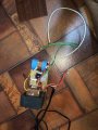
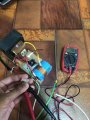
CAUTION: If the input testing supply transformer that provides 12-15VAC has a very high current capacity, then extreme caution should be taken when identifying the high voltage side. If your supply is a 12-15VAC transformer with 0.5 to 2Amps small transformer then the high voltage 115 or 220VAC will have a very low current capability and only a multimeter can show the voltage. Also a shock wouldn't be deadly in most cases. But as you can see in my setup the 15.8VAC source can pump close to 40 Amps. So, my 115VAC side has enough power to light the 120V-100W bulb (see IMG 004). In IMG 005 you can see the short circuit current is around 7 Amps. That level of current can be deadly if not handles cautiously.
Sorry, for the lengthy post. Feel free to provide provide your experiences and inputs in the comments below. Hope this helps someone.
Thanks.
I'm writing this post mainly to help others who have had asked many questions in the past how to figure out the input supply leads (115V or 220V AC wires) on a salvaged UPS transformer. These transformers from a UPS are quite bulky and quite powerful and can be very useful in making high current linear DC supplies by pairing it with a high current rectifier and good filter circuit. Recently I have been trying to build a high current 12VDC bench power supply.
So, I have three transformers in my possession; one is from an APC 1700VA rack UPS (pic transformer 1), next is from a Tripplite Internet 700VA UPS (pic transformer 2) & another from an APC BMC 300VA UPS (pic transformer 3). The The last UPS APC BMC 300VA had a smaller transformer also (pic transformer 4), which we will talk about later in the post.
A lot of times it is easy to identify the output side of a UPS transformer as the secondary low voltage-high current side has very thick wires usually around 14AWG to 10AWG for the higher current versions. In heavier massive UPS units they usually use multiple transformers rather than using a huge single transformer from what I have seen. Now, the secondary side can be quite confusing in some transformers if there are multiple connections and when all the wires are of the same AWG or thickness it becomes even more difficult to identify the correct wiring. Most of the well known UPS brands I have come across have a fixed input supply voltage rather than dual voltages i.e., they are either a 120VAC unit or a 240VAC unit. Though there could also be units with dual supply but its not very common as the manufacturer intends to sell it to region specifically where the outlet voltage is fixed. So, if your UPS unit is meant to run only on one particular voltage (120VAC or 240VAC) then it would make the identification of the leads much easier.
Now, coming to the testing part and identification of the primary leads of the transformer. To test the transformer on of the most recommended ways is to use the resistance method. But unfortunately a lot of UPS transformers that are only meant for a single supply have additional wires on primary side but are actually part of the secondary. In many UPS units there is a 15 to 17VAC output that is present along with the primary wires. I had read from one of the threads here that the 15 to 17VAC is actually to control the relays on the board (I'm not sure if this is correct, feel free to correct me please). In some transformers like the one in transformer 2 from Tripplite the two small orange colored wires are the 15VAC outputs and the thicker white - black wires are the 115VAC inputs which is easier to identify. But on the other hand in transformer 1 from APC the blue-yellow wires produce the 16.7VAC output. It can be quite confusing sometimes. Now, in the last transformer 3 from APC it doesn't have the 16VAC line but instead it had a small separate transformer 4 to obtain that 16VAC.
Most of the UPS output voltages are 15.3 to 15.7VAC without center tap and with center tap its 7.7VAC between the leads. So, to identify you need to obtain a 12VAC to 15VAC transformer or AC adapter. In my case I have used the Tripplite transformer 2 as my 15.3VAC source (see IMG 003) If you buy an AC adapter make sure the output is in AC voltage and not DC! If its DC just remove the rectifier + filter circuit and use the output from the transformer directly. Next feed the low voltage 12 - 15VAC supply to the thick secondary low voltage leads of the UPS transformer you are testing (in my case:see attachment IMG 004 & IMG 006). Avoid the center tap winding in the secondary (low voltage thick winding) of the UPS transformer. Now, take a multimeter and probe the primary side (thinner wires) of the UPS transformer. One pair of wires should give your in the range either from 100 - 127VAC or 200 - 240VAC (see attachment IMG 006). As mentioned above the other pair is usually the 16VAC output which can be ignored or if you want can be used as a second output for something (see attachment IMG007).
CAUTION: If the input testing supply transformer that provides 12-15VAC has a very high current capacity, then extreme caution should be taken when identifying the high voltage side. If your supply is a 12-15VAC transformer with 0.5 to 2Amps small transformer then the high voltage 115 or 220VAC will have a very low current capability and only a multimeter can show the voltage. Also a shock wouldn't be deadly in most cases. But as you can see in my setup the 15.8VAC source can pump close to 40 Amps. So, my 115VAC side has enough power to light the 120V-100W bulb (see IMG 004). In IMG 005 you can see the short circuit current is around 7 Amps. That level of current can be deadly if not handles cautiously.
Sorry, for the lengthy post. Feel free to provide provide your experiences and inputs in the comments below. Hope this helps someone.
Thanks.
Attachments
-
 2.7 MB Views: 56
 -
 3 MB Views: 67
 -
 3.5 MB Views: 57
 -
 2.7 MB Views: 61
 -
 1.8 MB Views: 53
 -
 2.7 MB Views: 45
 -
 2.8 MB Views: 51
 -
 3 MB Views: 53
 -
 3.1 MB Views: 51
 -
 3 MB Views: 48