 Facebook
 Google
 GitHub
 Linkedin
Hi Guys, I have made an Auto-Cleaning Add-on for an old swimming pool Chlorinator Control Unit.
The Control Unit is a non-autocleaning type which supplies low DC voltage (about 10V) high current (10-25A)
to a Salt Cell. When salty pool water runs through the Cell, chlorine gas is generated to clean the pool.
Since the Unit is a non-autocleaning type, it does not reverse DC polarity to the Cell to
clean the Cell periodically. The Add-on is used to help doing the polarity reversal job.
There are three wires (red, white, black) connecting between the Unit and the Cell. Red and black wires are
low voltage terminals and white is Gas sensing terminal which stops the Unit from outputing low voltage in case
gas is trapped in the Cell or there is no water flowing through the Cell.
During cleaning cycle, the Add-on breaks the Gas sensing wire in order to stop the Unit from outputing the low voltage.
However, the Control Unit does not work as expected (i.e. stops the output) but drops the current to about half.
As such, my Add-on cannot be used.
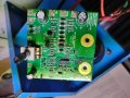
I would like to trace out the circuit diagram of the current output adjustment PCB inside the Unit, repair it and make it work as expected.
However, there is a 14-pin DIP SMD on the board that I cannot identify.
Referring to attached photo, its surface marking is something like "32 eZEP714". Is it some kind of PIC microcontroller or LM556 dual timer?
Would you guy please help me to identify the DIP.
The Control Unit is a non-autocleaning type which supplies low DC voltage (about 10V) high current (10-25A)
to a Salt Cell. When salty pool water runs through the Cell, chlorine gas is generated to clean the pool.
Since the Unit is a non-autocleaning type, it does not reverse DC polarity to the Cell to
clean the Cell periodically. The Add-on is used to help doing the polarity reversal job.
There are three wires (red, white, black) connecting between the Unit and the Cell. Red and black wires are
low voltage terminals and white is Gas sensing terminal which stops the Unit from outputing low voltage in case
gas is trapped in the Cell or there is no water flowing through the Cell.
During cleaning cycle, the Add-on breaks the Gas sensing wire in order to stop the Unit from outputing the low voltage.
However, the Control Unit does not work as expected (i.e. stops the output) but drops the current to about half.
As such, my Add-on cannot be used.
I would like to trace out the circuit diagram of the current output adjustment PCB inside the Unit, repair it and make it work as expected.
However, there is a 14-pin DIP SMD on the board that I cannot identify.
Referring to attached photo, its surface marking is something like "32 eZEP714". Is it some kind of PIC microcontroller or LM556 dual timer?
Would you guy please help me to identify the DIP.
Attachments
-
 1.3 MB Views: 20


