I want to know which factor causes switch node transient level high in buck converter

Thread Starter

Benengineer

Joined Feb 6, 2016
133
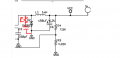
This is the circuit I have as follows:
upload_2016-7-5_17-11-12.png
Because the output noise is out of limits 120mV(P-P), which is 140mV. I added a capacitor and resistor to parallel with D2. The noise level reduce to 80mV. That is what I want. It is good enough for this level.
upload_2016-7-5_17-27-42.png

But this transient level is high. I want to know which factor causes this problem. My output is as follows:

upload_2016-7-5_17-26-15.png
Also, what suggestion do you want to give me, for example, you can tell me output capacitor C6 or inductor L1 changed? Thank you,
 

Attachments

DickCappels

Joined Aug 21, 2008
10,171
Also along the lines of Benengineer's thought that the inductor may be running "dry", is that if you are drawing the expected current then you should increase the value of your inductor.
 

Thread Starter

Benengineer

Joined Feb 6, 2016
133
Also along the lines of Benengineer's thought that the inductor may be running "dry", is that if you are drawing the expected current then you should increase the value of your inductor.
If inductor value is inreased, the peak current would be more smaller. I don't understand "inductor may be running "dry". "
Here is my calculation for peak current and capacitor value.
Based on buck, we can get ∆і = (Vin – Vo/2L) D Ts, this is how to design your L value according to your peak current.

I measured the parameters:

Vin = 24V Vo = 3.42V D= 11.5% Ts = 9.97uS

L is known parameter which is 1mH

∆і = 0.012A

The peak to peak voltage limits is 120mV. ∆V = 60mV

Then, I got ∆V = ∆і*Ts/8C. I can get min C = ∆і*Ts/8∆V

Cmin = 0.249uF.

The circuit shows 150uF. I think it is big enough. Please let me know what is wrong with this ripple?
 

crutschow

Joined Mar 14, 2008
34,431
This company is very wired. They don't know what load current is. Since this is a cable to communicate with others unit, I guess it is about 100mA.
Communication signals don't require significant power.
Guesses don't count. Unless we know the actual load current we can't answer your question.
Can you measure it?
 

Thread Starter

Benengineer

Joined Feb 6, 2016
133
This is just occupancy sensor and it is power by the cable which I showed many times in the circuit. So, I guess 3.3V is just power the unit itself. I measured input current at 24V is about 18.62mA. This is PCB board and I don't have a way to measure it. But I think it is less than 17mA. What is the reason you need to know the load? Do you have any theory to prove it?
 

Thread Starter

Benengineer

Joined Feb 6, 2016
133
Communication signals don't require significant power.
Guesses don't count. Unless we know the actual load current we can't answer your question.
Can you measure it?
When we design a buck, what if we don't have a load? Just think in this way, how to design switch frequency, what is network frequency. what about peak current, output peak voltage, design feedback loop. Duty cycle, how many poles, zero, how to adjust response with PID controller etc.
 

crutschow

Joined Mar 14, 2008
34,431
When we design a buck, what if we don't have a load? Just think in this way, how to design switch frequency, what is network frequency. what about peak current, output peak voltage, design feedback loop. Duty cycle, how many poles, zero, how to adjust response with PID controller etc.
When you design a buck converter, you need to know the maximum load current to do the design.
If you don't know that, then you need to know the actual load current.
 

Thread Starter

Benengineer

Joined Feb 6, 2016
133
When you design a buck converter, you need to know the maximum load current to do the design.
If you don't know that, then you need to know the actual load current.
Yes, we need to know the load. Since they don't know what the load is, I guess this is not critical parameter for them. It has been running for 20 years. As I told you, it is about 17mA at 3.3V. What suggestion can you give me?
Thanks,
 

Thread Starter

Benengineer

Joined Feb 6, 2016
133
And with a discontinuous current you will see that little triangular pulse that you do not like.
The discountinuoius mode happends at
I < ∆iɩ, which is 2L/RTѕ < D'(for buck duty cycle). That means the noise is bigger than the output if our assumatin is right. Is it possible for the diode reverse recoverary?
Thanks
 
Top