I need help with this circuit concerning polarity switch

Thread Starter

Cedric First

Joined Jun 19, 2017
6
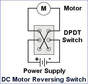
Hi guys! i'm getting stuck on this circuit. I know what i want but don't know how to do it... what i'm doing is a box that will have a lid which can open and close using a linear actuator(my own built one). what i want is that when i push a button (non momentary one i suppose) the actuator will push open the lid and when i push the button again the actuator will retract and close the lid. So i will be using a limit switch to kill power on the motor of the actuator when the box is fully opened and now at this stage i need to reverse polarity for the actuator to retract and when the lid is closed the limit switch will stop the motor again. So whatt i'm stuck on is the polarity switch, i want it to be a simple one push button and my original idea is to use if possible a touch sensor switch to replace the button, well does this exist a touch sensor switch that can reverse polarity? where can i buy this online? can i do this?
 

Thread Starter

Cedric First

Joined Jun 19, 2017
6
Thank you AlbertHall, your response helped me a lot! here is how i've illustrated how i would do it, and please hope you can confirm that it the right way?
circuit.png
 

AlbertHall

Joined Jun 4, 2014
12,345
Yes, providing the sensor can supply enough current for the relay coil. If not you may need something (a MOSFET?) between the sensor output and the relay coil.
 

Reloadron

Joined Jan 15, 2015
7,501
Take a good look at your drawing. Now look at Albert's example of using a switch. Your drawing won't work for several reasons. You also are not showing any limit switches.

Albert, would his drawing be correct? He is applying his battery across the N/O contacts so the only time any power is applied is when the relay is active and there is no direction change. That is what I see anyway and maybe I am not seeing this correctly?

Ron
 

AlbertHall

Joined Jun 4, 2014
12,345
Albert, would his drawing be correct? He is applying his battery across the N/O contacts so the only time any power is applied is when the relay is active and there is no direction change. That is what I see anyway and maybe I am not seeing this correctly?
You are correct. I didn't spot that the position of the connections are different to the switch drawing that I posted.
TS needs to cross-connect NO and NC connections and connect them to the motor. The battery should be connected to the COM terminals.
 

crutschow

Joined Mar 14, 2008
34,281
Here's the circuit with limit switches:
You probably should add diodes (4) across the relay contacts to minimize arcing from the motor inductance.

But you will need to add a circuit to alternate the relay position at each button push.
Here's such a circuit using a CD4013 flip-flop with simple debounce (discussed here if interested).
(Power and ground for the CD4013 aren't shown, and all unused inputs for the other FF in the package should be grounded.)
upload_2017-6-20_12-53-42.png
 
Last edited:

Thread Starter

Cedric First

Joined Jun 19, 2017
6
Yes I got confused between a relay and a switch I think, here is the competed drawing according to me.. I'm not sure about the positioning of the diodes but i think that's it?
circuit.png
 

AlbertHall

Joined Jun 4, 2014
12,345
Now you need to decide which touch sensor you are using and what its output is, then you can decide how to operate the relay coil with it.
 

Thread Starter

Cedric First

Joined Jun 19, 2017
6
I will be using this one
Capacitive-Touch-Sensor-Pin-Outs.png
This is the only one I've found that is suitable for me.
It says in the description that it can replace the traditional touch of a button.
I'm assuming that when the sensor is touched, it switch the relay to position 1 and remains and when touched again it switches to position 2 and remains. I think it works like a momentary switch..
The real picture.
s-l500.jpg
This is the link to it on aliexpress for more details: https://www.aliexpress.com/item/Dig...62.html?spm=2114.13010208.99999999.285.nokZpw
 

AlbertHall

Joined Jun 4, 2014
12,345
The chip on that board has a maximum output current of 8mA which will not be sufficient to operate the relay, so a MOSFET (the easiest way to do it) will be required.

You need a toggle action which the chip on that board can provide but I can find no details on how to make that selection on that board. As the board comes it appears to provide only momentary action - press the button operates the relay, release the button releases the relay, if I have correctly interpreted the text below from your link.

"The module is based on a touch-sensing IC (TTP223B) capacitive touch switch module. In the normal state, the module output low, low power consumption; When a finger touches the corresponding position, the module output high, if not touched for 12 seconds, switch to low-power mode.
Jog type : the initial state is low , high touch , do not touch is low ( similar touch of a button feature )"
 

Thread Starter

Cedric First

Joined Jun 19, 2017
6
So I'll add a MOSFET for the relay. The toggle action I think can only be made by this chip through Arduino as this module is mainly designated for Arduino... so does this feature (high/low power mode) affect the way my actuator will work? cause i understand that when I touch the sensor to open the box, the box opens and stays for about 12 seconds and will then close down? Am I right?and its not bad at all if it works like that... well I cannot surely determine those things i'm just a beginner and have very little experience with such circuits.. Would you recommend me to keep up with the idea of a sensor if it works? or stick to the DPDT switch version which is much easier.
 

Reloadron

Joined Jan 15, 2015
7,501
No, as drawn when the box opens it will open till it hits the limit switch and it will remain open till the relay opens. Using a single relay design as you have done the box will open till it trips a limit switch. It will remain open until the relay is deenergized at which point it will close the box till again it hits a limit switch.

When doing this with an Arduino or other uC (micro-controller) the uC would do all the thinking and timing. All of that would be handled in the code writtrn for the uC. This would explain the choice of switch used if the original design was uC based. Way back in the thread Mike suggested a circuit using a flip flop which short of a uC would be a good choice. I am not sure how your touch switch behaves? Do you have a link to the Arduino circuit?

Ron
 

AlbertHall

Joined Jun 4, 2014
12,345
i understand that when I touch the sensor to open the box, the box opens and stays for about 12 seconds and will then close down? Am I right?and its not bad at all if it works like that.
Yes, that's how I believe the sensor board works, if you touch briefly. I think if you keep your finger on the button then it will stay open.

[edit] Correction: I believe that touching the switch will open and releasing the button will close immediately. The 12 seconds is for it to switch to low power mode.

Will this circuit be running on a 5V supply, including the relay coil?
 

Reloadron

Joined Jan 15, 2015
7,501
I did some reading on your sensor and saw an application using Arduino. Catalex TTP223B Arduino Capacitive Touch Sensor. I also looked at the code sample. This leads me to believe the output goes high and remains high only while you are touching the sensor. Once a finger is removed the sensor output immediately goes low so the sensor is not a latch type device (touch for On and touch again for Off). So if you touch the sensor your actuator will start running and continue to run till either you release the touch sensor or you travel to a limit switch.

Based on your original post Carl offers a good solution in his post #9. Your sensor with one touch would "latch" a type D flip flop and with another touch un-latch the D flip flop.

One problem with a single DPST relay design is there is no off. Even with the relay deenergized the N/C contacts are in use so the motor (in this case) is always running in either forward or reverse. With a limit switch and the relay deenergized the relay will run the motor till you hit a limit. This may go better if you can actually state your objective and your working voltages.

I found the data sheet for the actual chip and according to the data sheet you can choose a "toggle Mode" the chip should be one of these.
The TTP223-BA6 is a touch pad detector IC which offers 1 touch key. The touching detection IC is designed for replacing traditional direct button key with diverse pad size. Low power consumption and wide operating voltage are the contact key features for DC or AC application.
So if the board allows setting an output mode you have some options.

Ron
 
Last edited:

crutschow

Joined Mar 14, 2008
34,281
Also you can avoid the need for diodes across the limit switches if you wire the relay and switches as shown in post #9.
You should probably still add them across the relay contacts.
 
Last edited:
Top