Facebook
 Google
 GitHub
 Linkedin
See that's pretty cool. Nooot getting my alertssss. Also do you think it possible to use an lm386 instead? If I have to change it around some that'll be fine with me.Hello,
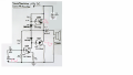
I just came accross a weird schematic that uses an opamp as driver for power transistor (founs in electuur):
View attachment 157882
They claim an output power of about 6 Watts @ 0.01 %
Bertus
I need help with an audio amplifier.
- Thread starter ConstructionK88
- Start date