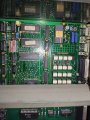
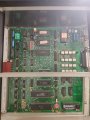
I need help. We want to repair our old test instrument.

schmitt trigger

Joined Jul 12, 2010
2,276
Speaking of the socketed CMOS:
Back then in the same time frame I repaired and maintained a large cassette-tape recording shop. The tapes were recorded at something like 50X the playback speed and the bias signal was frequency-scaled accordingly. The bias signal was buffered by a CD4069U with all six sections in parallel.
The service manual clearly indicated that in case of a device replacement, several ICs should be procured and tested. With a scope one would hand-select the one with the better symmetrical waveform.
Motorola Semi always gave good results.
 

Thread Starter

menemenli

Joined Jun 17, 2011
15
Speaking of the socketed CMOS:
Back then in the same time frame I repaired and maintained a large cassette-tape recording shop. The tapes were recorded at something like 50X the playback speed and the bias signal was frequency-scaled accordingly. The bias signal was buffered by a CD4069U with all six sections in parallel.
The service manual clearly indicated that in case of a device replacement, several ICs should be procured and tested. With a scope one would hand-select the one with the better symmetrical waveform.
Motorola Semi always gave good results.
:) Awesome experience.
 

Futurist

Joined Apr 8, 2025
950
I wonder if those EPROMS have lost data, they are at least 33 years old, that's pushing it. It might be a good idea to back them up anyway.
 
Last edited:

Werecow

Joined Aug 4, 2025
37
Another comment about the ICs in sockets: Time, heating/cooling cycles, oxidation and dust are enemies of sockets. It wouldn't hurt to remove and re-seat the socketed parts, to renew the connections. If that makes any difference (for better or worse), a good cleaning of both the ICs and sockets with DeoxIT or similar cleaner, and a stiff brush, might be in order.
 

Thread Starter

menemenli

Joined Jun 17, 2011
15
Another comment about the ICs in sockets: Time, heating/cooling cycles, oxidation and dust are enemies of sockets. It wouldn't hurt to remove and re-seat the socketed parts, to renew the connections. If that makes any difference (for better or worse), a good cleaning of both the ICs and sockets with DeoxIT or similar cleaner, and a stiff brush, might be in order.
Thanks for the advice.

I am checking PCB, ICs and sockets now. I do re-seat ICs
 

dl324

Joined Mar 30, 2015
18,491
We checked them. They are fine.
How do you really know?

Since data retention depends on charge remaining on the floating gate, you should also read them at low VCC (or slightly lower) and compare the data with data read at high VCC.

I've intentionally made EPROMs that read as erased at 5V and read as programmed at 4.5V just to prove a point about sufficient erase margin. Professional programmers may not give you the ability to do that. I have some homebrew Willem programmers that I've modified to allow me to vary the voltages for erase and program verification.
 

Thread Starter

menemenli

Joined Jun 17, 2011
15
How do you really know?

Since data retention depends on charge remaining on the floating gate, you should also read them at low VCC (or slightly lower) and compare the data with data read at high VCC.

I've intentionally made EPROMs that read as erased at 5V and read as programmed at 4.5V just to prove a point about sufficient erase margin. Professional programmers may not give you the ability to do that. I have some homebrew Willem programmers that I've modified to allow me to vary the voltages for erase and program verification.
How do you really know?

Since data retention depends on charge remaining on the floating gate, you should also read them at low VCC (or slightly lower) and compare the data with data read at high VCC.

I've intentionally made EPROMs that read as erased at 5V and read as programmed at 4.5V just to prove a point about sufficient erase margin. Professional programmers may not give you the ability to do that. I have some homebrew Willem programmers that I've modified to allow me to vary the voltages for erase and program verification.

Well, there are checksum values on small stickers on the EPROMs. They are verified by the programmer device (xeltek superpro)

Also, we tried to read multiple times, and we read the same data.
 

Attachments

dl324

Joined Mar 30, 2015
18,491
Also, we tried to read multiple times, and we read the same data.
Reading multiple times under the same voltage conditions doesn't tell you much. If the low voltage read compared the same to the high voltage read, then you're good.

If the checksums were okay, then you're likely okay. The only problem would be if there were bits that were marginal at the read voltage. Reads at high and low VCC would tell you if you had marginal bits at about the nominal voltage.
 

Thread Starter

menemenli

Joined Jun 17, 2011
15
Reading multiple times under the same voltage conditions doesn't tell you much. If the low voltage read compared the same to the high voltage read, then you're good.

If the checksums were okay, then you're likely okay. The only problem would be if there were bits that were marginal at the read voltage. Reads at high and low VCC would tell you if you had marginal bits at about the nominal voltage.
I got what you mean.

Today i completed first check of the electronics and I turn on the instrument.
Everything is same as the beggining. The instrument repeat the same thing.

I am afraid, i was wrong. it is probably a bootloop.
The program is not functioning, not running.
Something is reseting the software.

How can i figure out the bootloop?

I tried the push the reset button that is next to cpu. Unfortunately the reaction makes me feel bad about the situation.
Because whenever i press the reset button, the instrument do the same thing that it does when it is idle, waiting.

I had supposed that it was waiting a good IR signal or searching a home position etc.
I am afraid, i was wrong. it is a bootloop.

I am keeping on digging.
 

Attachments

MrChips

Joined Oct 2, 2009
35,279
Sorry for not being able to contribute earlier.

The EPROMS are marked with being programmed in 1992.
The first thing I would do is check all supply voltages with DMM and oscilloscope.
Certainly, replace the 3.6 V battery, after cleaning that section of the board with isopropyl alcohol.

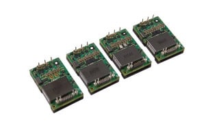
Datasheet for Reliablity V5R12-12 is posted here.
https://www.silicon-ark.co.uk/datasheets/v-pac_s-pac-dc-converters-reliability.pdf

Check voltages with DMM and oscilloscope.

Hold the circuit in RESET mode and check all the pins on the MC6802P with oscilloscope.
Release RESET and check again.
https://pccomponents.com/datasheets/MOTO-MC6802.PDF

Basically, we are looking for stuck data, address, control bits.

Continue on to the 27C64 EPROM pins.
Do the same with the M5M51008P 128K x 8 SRAM.

If possible, try and reverse engineer the circuit by keeping track of what is connected to what.
There are still other peripheral chips to check out:
MC6821P - PIA = Peripheral Interface Adapter
MC6840P - PTM = Programmable Timer Module
MC6850P - ACIA = Asynchronous Communications Interface Adapter (UART)

There is an address decoder chip (device select) which we will look into later.

That should keep you busy for a while.
 
Top