Facebook
 Google
 GitHub
 Linkedin
Hello to everyone ")
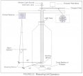
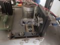
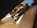
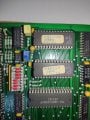
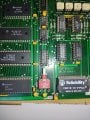
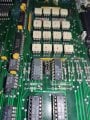
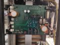
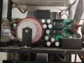
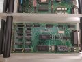
I need help. We want to repair our old test instrument. It measures thickness and dimensional attributes of plastic (PET etc) containers and preforms.
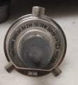
It is a Topwave Gawis. It was made in 1992 by TOPWAVE company. Its manufacturer is already in the dusty pages of history.
There is a few information about it on internet. A video in youtube about it; its title is :"Material Distribution with the Gawis TopWave":
We have only a manual and a few emails about some faults. However not enough.
Also there isn't any user/operator of the instrument.
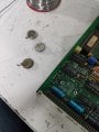
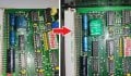
There is a principle of operation sheet attached.
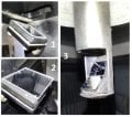
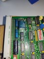
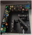
And also photos of the instrument.
Is there anybody who can help me about it?
Any documents, any ideas, whatever.
Thanks so much.


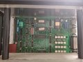
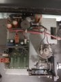
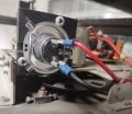
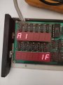
I need help. We want to repair our old test instrument. It measures thickness and dimensional attributes of plastic (PET etc) containers and preforms.
It is a Topwave Gawis. It was made in 1992 by TOPWAVE company. Its manufacturer is already in the dusty pages of history.
There is a few information about it on internet. A video in youtube about it; its title is :"Material Distribution with the Gawis TopWave":
We have only a manual and a few emails about some faults. However not enough.
Also there isn't any user/operator of the instrument.
There is a principle of operation sheet attached.
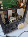
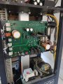
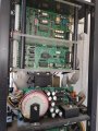
And also photos of the instrument.
Is there anybody who can help me about it?
Any documents, any ideas, whatever.
Thanks so much.