Now I mounted the capacitor in parallel with the power pins of the motor, and also I see you inserted a circuit in your previeous post. This is now as in your circuit as well. But still no kick and not running either. If I spin the rotor VERY slowly, it get stuck at very random locations, sign that the coil is working but in a very weird way.
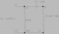
The capacitor is NOT wired across the supply, it is in SERIES with the start winding
The run winding is directly across the supply.
It should be wired as per #16 & #18.
I did not change my DWG.
you mean this?
damn... that is an old notation, that means those pins are connected and not interrupted and indicates it has a resistance of xx value between them. I should change that old notation with a winding for avoiding any errors... I made it so I got used to it. Sorry.
I looked closely to your last diagram and it says there is an electrolytic capacitor, so I tried one but... still nothing.
I changed its polarity on the pins but still, nothing.
I also corrected my old simple wire connection with a winding that is looking more as an american resistor symbol now. Eh well, better than a simple wire connection as it was before.
Oh, YES, I didnt touch those wiring. , but B2 and C1 was connected together externally with a wire,on the other motor as I discovered later.
In this picture, that left brown wire appear is connected to the black wire, but is the angle of the camera this way, in reality, is going back behind into the motor.
That was not mine, that was @vu2nan !
Again, what is the resistance from each on post #26?
If you list them i can give a you a detailed schematic.
You cannot use those capacitors to run a motor they will blow.
They have to be motor-run rated. Oil filled etc.
You are right, a circuit is better to have at this point to clarify what is what.
Here it is: (I even color coded every wire)
Like I said, I discovered there was a wire link externally, but was bend under the motor and I thought there were some cut wires as well, but when I dragged the wire more, surprise, was a link on B2 and C1 as shown and explained already.
Maybe is the fault of the variac that is providing only 1 phase ?
Working with a variac is pretty new to me so, it is a variable for me until I will learn it better and get used to it.
Although I seen some guys on youtube driving very happily their motors with a variac and driving more electronics just fine.
I measured the output of my variac and it is working perfectly, my DMM is getting an alternative variable voltage from its output. For sure is doing its thing. But maybe that 1 phase is a problem for this specific motor? Im just putting ideas on the table.
I know, but im at that point I try everything, haha.
You are right, a circuit is better to have at this point to clarify what is what.
Here it is: (I even color coded every wire) View attachment 264979
Like I said, I discovered there was a wire link externally, but was bend under the motor and I thought there were some cut wires as well, but when I dragged the wire more, surprise, was a link on B2 and C1 as shown and explained already.
I tell you what. Try to make My circuit and redraw the wires over it. But keep my configuration I already have.
Draw on a piece of paper and take a picture of it, and post it here.
NO, you show the capacitor across the supply which I do NOT show, it is in series with the start winding!
I have just taken your description of the connections in #30 and explained what should be connected, in #33.
This is how it should operate if it is a simple 1ph start-run winding induction motor.
There is not much to understand, you don't need to change the anything, just hook up very simple.
Im trying to do what you tell me as much as I can understand you.
I hear you, that you said I should not put the capacitor across the supply power pins.
And also you mentioned that the bigger resistance coil should have that capacitor over it...
so I draw this new version, is this closer to what you trying to say to me?
I didnt wait for your response and I wired it as in my last diagram.
And guess what? It is spinning ! Evrika!
Not as fast as I wish but it is spinning by itself. Amazing! after what? 30years? Ohohoa... Super!
I am now thinking maybe to put a capacitor on the second coil as well? WHat do you say?
I assembled the second motor and test it like the first and it is spinning.
So both are working ! No one is burned. Wow. Im very happy.
The speed and power is extremely low, I dont see I can make anything useful with either of them... Ill have to think very hard to find a practical usage of these motors. And definetly I will not make a magnetofon with them, haha.
 Facebook
 Google
 GitHub
 Linkedin